LG 47LH30FR-MA Owner's Manual - Page 31
How To Secure The Power Cable
 |
View all LG 47LH30FR-MA manuals
Add to My Manuals
Save this manual to your list of manuals |
Page 31 highlights
MFL58486305-Edit1-en 10/21/09 11:08 AM Page 29 For 19LU50R, 22/26LU50FR, 22LU40R 1 After connecting the cables as necessary, install CABLE HOLDER as shown and bundle the cables. For 32/42/47LH70YR 1 Align the hole with the tab on the CABLE MANAGEMENT CLIP. Turn the CABLE MANAGEMENT CLIP as shown. Note: This cable management clip can be broken by excessive pressure. 2 Connect the cables as necessary. To connect additional equipment, see the EXTERNAL EQUIPMENT SETUP section. HOW TO SECURE THE POWER CABLE Secure the power cable with the PROTECTIVE BRACKET and the bolt as shown. It will help prevent the power cable from being removed by accident. SCREW PROTECTIVE BRACKET 29 PREPARATION
-
 1
1 -
2
-
3
-
4
-
5
-
6
-
7
-
8
-
9
-
10
-
11
-
12
-
13
-
14
-
15
-
16
-
17
-
18
-
19
-
20
-
21
-
22
-
23
-
24
-
25
-
 26
26 -
 27
27 -
 28
28 -
 29
29 -
 30
30 -
 31
31 -
 32
32 -
 33
33 -
 34
34 -
 35
35 -
 36
36 -
37
-
38
-
39
-
40
-
41
-
42
-
43
-
44
-
45
-
46
-
47
-
48
-
49
-
50
-
51
-
52
-
53
-
54
-
55
-
56
-
57
-
58
-
59
-
60
-
61
-
62
-
63
-
64
-
65
-
66
-
67
-
68
-
69
-
70
-
71
-
72
-
73
-
74
-
75
-
76
-
77
-
78
-
79
-
80
-
81
-
82
-
83
-
84
-
85
-
86
-
87
-
88
-
89
-
90
-
91
-
92
-
93
-
94
-
95
-
96
-
97
-
98
-
99
-
100
-
101
-
102
-
103
-
104
-
105
-
106
-
107
-
108
-
109
-
110
-
111
-
112
-
113
-
114
-
115
-
116
-
117
-
118
-
119
-
120
-
121
-
122
-
123
-
124
-
125
-
126
-
127
-
128
-
129
-
130
-
131
-
132
-
133
-
134
-
135
-
136
-
137
-
138
-
139
-
140
-
141
-
142
-
143
-
144
-
145
-
146
-
147
-
148
-
149
-
150
-
151
-
152
-
153
-
154
-
155
-
156
-
157
-
158
-
159
-
160
-
161
-
162
-
163
-
164
-
165
-
166
-
167
-
168
-
169
-
170
-
171
-
172
-
173
-
174
-
175
-
176
-
177
-
178
-
179
-
180
-
181
-
182
-
183
-
184
-
185
-
186
-
187
-
188
-
189
-
190
-
191
-
192
-
193
-
194
-
195
-
196
-
197
-
198
-
199
-
200
-
201
-
202
-
203
-
204
-
205
-
206
-
207
-
208
-
209
-
210
-
211
-
212
-
213
-
214
-
215
-
216
-
217
-
218
-
219
-
220
-
221
-
222
-
223
-
224
-
225
-
226
-
227
-
228
-
229
-
230
-
231
-
232
-
233
-
234
-
235
-
236
-
237
-
238
-
239
-
240
-
241
-
242
-
243
-
244
-
245
-
246
-
247
-
248
-
249
-
250
-
251
-
252
-
253
-
254
 |
 |
PREPARATION
29
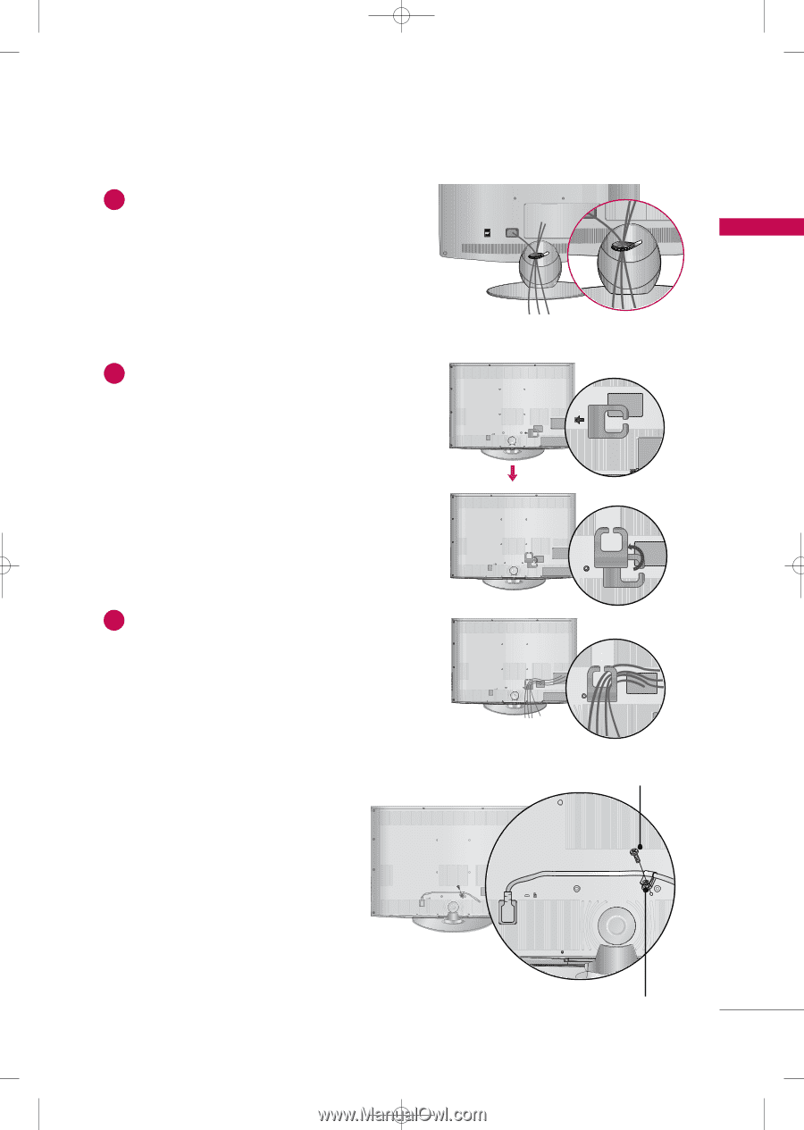
Align the hole with the tab on the
CABLE
MANAGEMENT CLIP
.
Turn the
CABLE MANAGEMENT CLIP
as
shown.
Note: This cable management clip can be bro-
ken by excessive pressure.
Connect the cables as necessary.
To connect additional equipment, see the
EXTERNAL EQUIPMENT SETUP
section.
1
2
HOW TO SECURE THE POWER CABLE
Secure the power cable with the
PROTECTIVE
BRACKET
and the bolt as shown. It will help pre-
vent the power cable from being removed by acci-
dent.
PROTECTIVE BRACKET
SCREW
For 32/42/47LH70YR
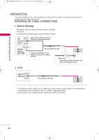
For 19LU50R, 22/26LU50FR, 22LU40R
After connecting the cables as necessary,
install
CABLE HOLDER
as shown and bundle
the cables.
1
MFL58486305-Edit1-en
10/21/09 11:08 AM
Page 29