LG M6100 Service Manual - Page 107
D. Procedure
 |
View all LG M6100 manuals
Add to My Manuals
Save this manual to your list of manuals |
Page 107 highlights
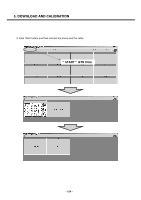
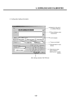
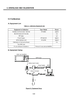
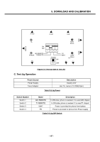
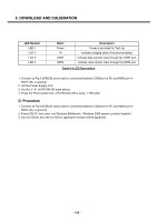
5. DOWNLOAD AND CALIBRATION LED Number LED 1 LED 2 LED 3 LED 4 Name Power TA UART MON Description Power is provided for Test Jig Indicate charging state of the phone battery Indicate data transfer state through the UART port Indicate data transfer state through the MON port Table 5-4 LED Description 1. Connect as Fig 6-2(RS232 serial cable is connected between COM port of PC and MON port of TEST JIG, in general) 2. Set the Power Supply 4.0V 3. Set the 3rd, 4th of DIP SW ON state always 4. Press the Phone power key, if the Remote ON is used, 1st ON state D. Procedure 1. Connect as Fig 6-2(RS232 serial cable is connected between COM port of PC and MON port of TEST JIG, in general) 2. Power ON PC then enter into Windows 98(Remark : Windows 2000 system could be feasible) 3. Run AUTOCAL.exe, the AUTOCAL application window will be appeared. - 108 -
-
 1
1 -
2
-
3
-
4
-
5
-
6
-
7
-
8
-
9
-
10
-
11
-
12
-
13
-
14
-
15
-
16
-
17
-
18
-
19
-
20
-
21
-
22
-
23
-
24
-
25
-
26
-
27
-
28
-
29
-
30
-
31
-
32
-
33
-
34
-
35
-
36
-
37
-
38
-
39
-
40
-
41
-
42
-
43
-
44
-
45
-
46
-
47
-
48
-
49
-
50
-
51
-
52
-
53
-
54
-
55
-
56
-
57
-
58
-
59
-
60
-
61
-
62
-
63
-
64
-
65
-
66
-
67
-
68
-
69
-
70
-
71
-
72
-
73
-
74
-
75
-
76
-
77
-
78
-
79
-
80
-
81
-
82
-
83
-
84
-
85
-
86
-
87
-
88
-
89
-
90
-
91
-
92
-
93
-
94
-
95
-
96
-
97
-
98
-
99
-
100
-
101
-
 102
102 -
 103
103 -
 104
104 -
 105
105 -
 106
106 -
 107
107 -
 108
108 -
 109
109 -
 110
110 -
 111
111 -
 112
112 -
113
-
114
-
115
-
116
-
117
-
118
-
119
-
120
-
121
-
122
-
123
-
124
-
125
-
126
-
127
-
128
-
129
-
130
-
131
-
132
-
133
-
134
-
135
-
136
-
137
-
138
-
139
-
140
-
141
-
142
-
143
-
144
-
145
-
146
-
147
-
148
-
149
-
150
-
151
-
152
-
153
-
154
-
155
-
156
-
157
-
158
-
159
-
160
 |
 |