LG M6100 Service Manual - Page 47
Microphone, 11 Main Speaker
 |
View all LG M6100 manuals
Add to My Manuals
Save this manual to your list of manuals |
Page 47 highlights
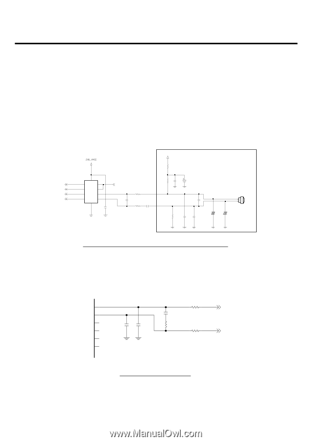
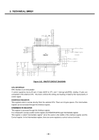
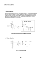
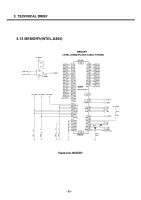
3. TECHNICAL BRIEF 3.10 Microphone The microphone is placed to the front cover and contacted to main PCB. The audio signal is passed to AIN1P and AININ pins of AD6535. The voltage supply VMIC is output from AD6535, and is a biased voltage for the AIN1P. The AIN1P and AIN1N signals are then A/D converted by the voiceband ADC part of AD6535.The digitized speech (PCM 8KHz ,16KHz) is then passed to the DSP section of AD6527B for processing (coding, interleaving etc). MULTI_MIC_P MULTI_MIC_N VINNORP VINNORN U201 MAX4684EBC_T V+ B4 C4 NO1 A4 NO2 C1 NC1 A1 NC2 C2 IN1 A2 IN2 C3 COM1 A3 COM2 GND B1 C210 1u MIC_PATH_SEL C206 R206 100 39p R208 100 C208 0.1u 2V5_VMIC R202 1K CLOSE TO MIC R203 C203 2.2K 39p C201 10u C207 39p OSF213-42D 1 2 MIC201 R211 2.2K C212 39p C213 39p VA201 EVL14K02200 VA202 EVL14K02200 Figure 3-23. Connection between Microphone and AD6535 3.11 Main Speaker B8 SPOUT2L B7 SPOUT1L H8 SPOUT2R J8 SPOUT1R E8 TXOUT D7 EXTOUT C743 C744 47p 47p C742 NA R732 NA R731 0 R733 0 Close to SPEAKER SPK_N SPK_P Figure 3-24. MAIN SPEAKER - 48 -
-
 1
1 -
2
-
3
-
4
-
5
-
6
-
7
-
8
-
9
-
10
-
11
-
12
-
13
-
14
-
15
-
16
-
17
-
18
-
19
-
20
-
21
-
22
-
23
-
24
-
25
-
26
-
27
-
28
-
29
-
30
-
31
-
32
-
33
-
34
-
35
-
36
-
37
-
38
-
39
-
40
-
41
-
 42
42 -
 43
43 -
 44
44 -
 45
45 -
 46
46 -
 47
47 -
 48
48 -
 49
49 -
 50
50 -
 51
51 -
 52
52 -
53
-
54
-
55
-
56
-
57
-
58
-
59
-
60
-
61
-
62
-
63
-
64
-
65
-
66
-
67
-
68
-
69
-
70
-
71
-
72
-
73
-
74
-
75
-
76
-
77
-
78
-
79
-
80
-
81
-
82
-
83
-
84
-
85
-
86
-
87
-
88
-
89
-
90
-
91
-
92
-
93
-
94
-
95
-
96
-
97
-
98
-
99
-
100
-
101
-
102
-
103
-
104
-
105
-
106
-
107
-
108
-
109
-
110
-
111
-
112
-
113
-
114
-
115
-
116
-
117
-
118
-
119
-
120
-
121
-
122
-
123
-
124
-
125
-
126
-
127
-
128
-
129
-
130
-
131
-
132
-
133
-
134
-
135
-
136
-
137
-
138
-
139
-
140
-
141
-
142
-
143
-
144
-
145
-
146
-
147
-
148
-
149
-
150
-
151
-
152
-
153
-
154
-
155
-
156
-
157
-
158
-
159
-
160
 |
 |