LG M6100 Service Manual - Page 37
Charging IC ISL6299, U401
 |
View all LG M6100 manuals
Add to My Manuals
Save this manual to your list of manuals |
Page 37 highlights
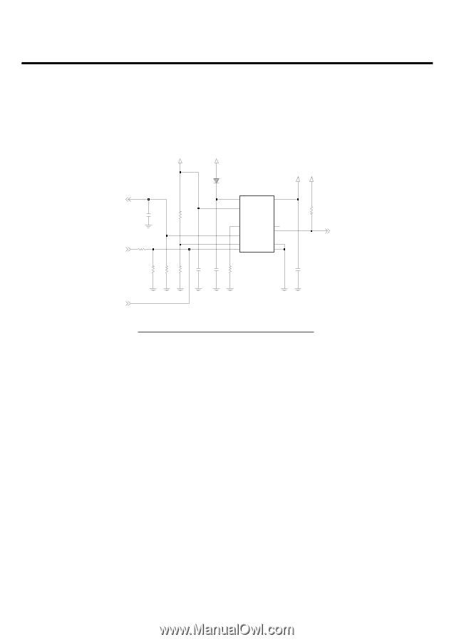
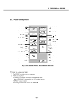
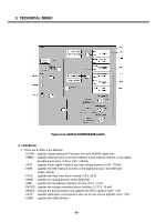
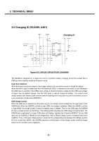
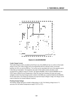
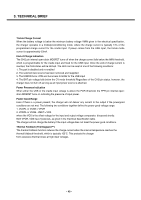
3. TECHNICAL BRIEF 3.6 Charging IC (ISL6299, U401) CUR_MON (ABB AUX2) CHG_EN (GPIO0) VUSBIN VCHARGE Charging IC C407 NA R405 10K R406 0 R410 (1%) R408 R411 10K 39K 10K C411 1u D401 CUS02 U402 1 CRDL BAT 10 2 USB 6 IMIN 9 ICDL _PPR 3 _CHG 4 7 5 USBON _EN GND 8 11 PGND ISL6299 C412 R409 1u 100K VBAT 2V8_VEXT R403 10K CHG_STAT C413 1u CHG_EN_IO Figure 3-16. CIRCUIT FOR BATTERY CHARGING The ISL6299 is designed for a single-cell Li-ion or Li-polymer battery charging circuit that accepts both a USB port and a desktop cradle as its power source. Input Auto Selection When both input sources are present, the charger selects only one power source to charge the battery. When the CRDL input is higher than the POR threshold, CRDL is selected as the power source. Otherwise the USB input is selected. If the CRDL input voltage is below the battery voltage but the USB input voltage is higher than the battery voltage, then the USB input is used to charge the battery. The control circuit always breaks both internal power devices before switching from one power source to the other to avoid a cross conduction of both power MOSFETs. USB Charge Current When the USB port is selected as the power source, the charge current enabled by the logic input at the USBON pin. When the USBON is driven to logic LOW, the charger is disabled. When the USBON is driven to logic HIGH, the charge current is fixed at a typical value of 380mA. Thus for the USB input, the USBON pin has a similar function as the EN pin. The following table describes the USB charge control by both The USBON pin is equivalent to a logic LOW when left floating. Typically the P-channel MOSFET for the USB input has an rDS(ON) of 700mΩ at room temperature. With a 380mA charge current, the typical head room is 260mV. Thus, if the input voltage drops to a level that the voltage difference between the USB pin and the BAT pin is less than 260mV, the rDS(ON) becomes a limiting factor of the charge current; and the charger drops out the constant current regulation. - 38 -
-
 1
1 -
2
-
3
-
4
-
5
-
6
-
7
-
8
-
9
-
10
-
11
-
12
-
13
-
14
-
15
-
16
-
17
-
18
-
19
-
20
-
21
-
22
-
23
-
24
-
25
-
26
-
27
-
28
-
29
-
30
-
31
-
 32
32 -
 33
33 -
 34
34 -
 35
35 -
 36
36 -
 37
37 -
 38
38 -
 39
39 -
 40
40 -
 41
41 -
 42
42 -
43
-
44
-
45
-
46
-
47
-
48
-
49
-
50
-
51
-
52
-
53
-
54
-
55
-
56
-
57
-
58
-
59
-
60
-
61
-
62
-
63
-
64
-
65
-
66
-
67
-
68
-
69
-
70
-
71
-
72
-
73
-
74
-
75
-
76
-
77
-
78
-
79
-
80
-
81
-
82
-
83
-
84
-
85
-
86
-
87
-
88
-
89
-
90
-
91
-
92
-
93
-
94
-
95
-
96
-
97
-
98
-
99
-
100
-
101
-
102
-
103
-
104
-
105
-
106
-
107
-
108
-
109
-
110
-
111
-
112
-
113
-
114
-
115
-
116
-
117
-
118
-
119
-
120
-
121
-
122
-
123
-
124
-
125
-
126
-
127
-
128
-
129
-
130
-
131
-
132
-
133
-
134
-
135
-
136
-
137
-
138
-
139
-
140
-
141
-
142
-
143
-
144
-
145
-
146
-
147
-
148
-
149
-
150
-
151
-
152
-
153
-
154
-
155
-
156
-
157
-
158
-
159
-
160
 |
 |