LG M6100 Service Manual - Page 27
D. SIM interface, E. Key interface, F. AD6535 Interrupt
 |
View all LG M6100 manuals
Add to My Manuals
Save this manual to your list of manuals |
Page 27 highlights
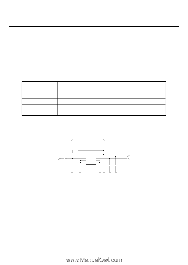
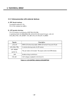
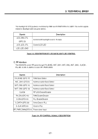
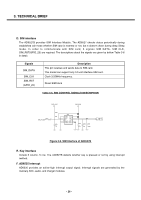
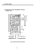
3. TECHNICAL BRIEF D. SIM interface The AD6527B provides SIM Interface Module. The AD6527 checks status periodically during established call mode whether SIM card is inserted or not, but it doesn't check during deep Sleep mode. In order to communicate with SIM card, 3 signals SIM_DATA, SIM_CLK, SIM_RST(GPIO_23) are required. The descriptions about the signals are given by bellow Table 3-6 in detail. Signals SIM_DATA SIM_CLK SIM_RST (GPIO_23) Description This pin receives and sends data to SIM card. This model can support only 3.0 volt interface SIM card. Clock 3.25MHz frequency. Reset SIM block Table 3-5. SIM CONTROL SIGNALS DESCRIPTION 2V85_VSIM 2V85_VSIM R362 0 SIM_DATA R361 20K C321 NA J301 4 5 GND1 VCC 1 2 6 VPP IO RST CLK 3 10 9 GND5 GND2 7 8 GND4 GND3 C320 220n C322 C323 27p 1000p SIM_RST SIM_CLK Figure 3-6. SIM Interface of AD6527B E. Key interface Include 5 column, 5 row. The AD6527B detects whether key is pressed or not by using interrupt method. F. AD6535 Interrupt AD6535 provides an active-high interrupt output signal. Interrupt signals are generated by the Auxiliary ADC, audio, and charger modules. - 28 -
-
 1
1 -
2
-
3
-
4
-
5
-
6
-
7
-
8
-
9
-
10
-
11
-
12
-
13
-
14
-
15
-
16
-
17
-
18
-
19
-
20
-
21
-
 22
22 -
 23
23 -
 24
24 -
 25
25 -
 26
26 -
 27
27 -
 28
28 -
 29
29 -
 30
30 -
 31
31 -
 32
32 -
33
-
34
-
35
-
36
-
37
-
38
-
39
-
40
-
41
-
42
-
43
-
44
-
45
-
46
-
47
-
48
-
49
-
50
-
51
-
52
-
53
-
54
-
55
-
56
-
57
-
58
-
59
-
60
-
61
-
62
-
63
-
64
-
65
-
66
-
67
-
68
-
69
-
70
-
71
-
72
-
73
-
74
-
75
-
76
-
77
-
78
-
79
-
80
-
81
-
82
-
83
-
84
-
85
-
86
-
87
-
88
-
89
-
90
-
91
-
92
-
93
-
94
-
95
-
96
-
97
-
98
-
99
-
100
-
101
-
102
-
103
-
104
-
105
-
106
-
107
-
108
-
109
-
110
-
111
-
112
-
113
-
114
-
115
-
116
-
117
-
118
-
119
-
120
-
121
-
122
-
123
-
124
-
125
-
126
-
127
-
128
-
129
-
130
-
131
-
132
-
133
-
134
-
135
-
136
-
137
-
138
-
139
-
140
-
141
-
142
-
143
-
144
-
145
-
146
-
147
-
148
-
149
-
150
-
151
-
152
-
153
-
154
-
155
-
156
-
157
-
158
-
159
-
160
 |
 |