LG M6100 Service Manual - Page 19
Transmitter Part
 |
View all LG M6100 manuals
Add to My Manuals
Save this manual to your list of manuals |
Page 19 highlights
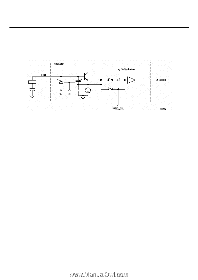
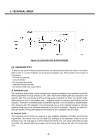
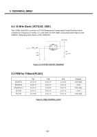
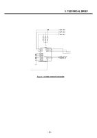
3. TECHNICAL BRIEF Figure. 3-2 Crystal Oscillator BLOCK DIAGRAM (3) Transmitter Part To minimize the post-PA filtering requirements and any additional post-power amp losses, the transmit path consists of a vector modulator and a frequency translation loop. The translation loop consists of the following: • PFD and charge pump • In-loop modulator • One programmable divider • Integrated transmit loop filter • Two transmit VCOs and output buffers A. Translation Loop The translational loop includes a vector modulator and a frequency translation loop to minimize the post-PA filtering requirements. the loop functions as a PLL with a mixer in the feedback path and a modulator in the reference path. The loop provides a PFD and charge pump, integrated loop filters, two transmit VCOs, down-conversion mixer in the feedback path, a frequency divider for frequency plan flexibility, and the modulator. The mixers in the feedback path provide either high side or low side injection to provide flexibility in the frequency plan. The modulator in the reference path uses a vector summing technique to reject the unwanted image and to also sufficiently attenuate the 3rd and 5th harmonics. Therefore, no external IF filters are required. The loop filter required for the transmit VCOs is integrated in the SKY74400. B. Transmit VCOs Two integrated transmit VCOs are designed to meet GSM850, EGSM900, DCS1800, and PCS1900 requirements. The transmit VCOs use the same DFC technique as the synthesizer section to lock the translation loop. The rising edge on TXENA initializes the transmit DFC. The output buffers feed the signal to the PAs. Two transmit buffers are provided, one for the low band VCO and the other for the high band VCO. - 20 -
-
 1
1 -
2
-
3
-
4
-
5
-
6
-
7
-
8
-
9
-
10
-
11
-
12
-
13
-
 14
14 -
 15
15 -
 16
16 -
 17
17 -
 18
18 -
 19
19 -
 20
20 -
 21
21 -
 22
22 -
 23
23 -
 24
24 -
25
-
26
-
27
-
28
-
29
-
30
-
31
-
32
-
33
-
34
-
35
-
36
-
37
-
38
-
39
-
40
-
41
-
42
-
43
-
44
-
45
-
46
-
47
-
48
-
49
-
50
-
51
-
52
-
53
-
54
-
55
-
56
-
57
-
58
-
59
-
60
-
61
-
62
-
63
-
64
-
65
-
66
-
67
-
68
-
69
-
70
-
71
-
72
-
73
-
74
-
75
-
76
-
77
-
78
-
79
-
80
-
81
-
82
-
83
-
84
-
85
-
86
-
87
-
88
-
89
-
90
-
91
-
92
-
93
-
94
-
95
-
96
-
97
-
98
-
99
-
100
-
101
-
102
-
103
-
104
-
105
-
106
-
107
-
108
-
109
-
110
-
111
-
112
-
113
-
114
-
115
-
116
-
117
-
118
-
119
-
120
-
121
-
122
-
123
-
124
-
125
-
126
-
127
-
128
-
129
-
130
-
131
-
132
-
133
-
134
-
135
-
136
-
137
-
138
-
139
-
140
-
141
-
142
-
143
-
144
-
145
-
146
-
147
-
148
-
149
-
150
-
151
-
152
-
153
-
154
-
155
-
156
-
157
-
158
-
159
-
160
 |
 |