Lenovo ThinkCentre A58e Hardware Maintenance Manual - Page 71
Replacing FRUs (Type 0841), Locations, Rear connectors
 |
View all Lenovo ThinkCentre A58e manuals
Add to My Manuals
Save this manual to your list of manuals |
Page 71 highlights
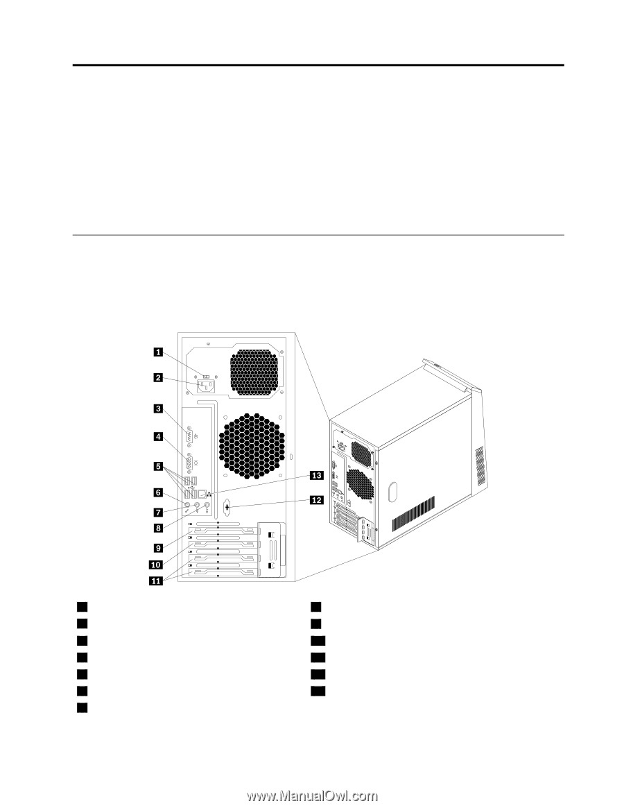
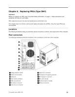
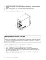
Chapter 8. Replacing FRUs (Type 0841) Important Before you replace any FRU, read "Important Safety Information" on page 1. These precautions and guidelines will help you work safely. FRU replacements are to be done by trained service technicians only. This chapter does not contain a remove and replace procedure for all FRUs. Only the major FRUs are documented. Locations The following illustrations help you locate the various connectors, controls. and components of the computer. Rear connectors The following illustration shows the locations of the connectors on the rear of the computer. 1 Voltage-selection switch 2 Power cord connector 3 Serial port 4 VGA monitor connector 5 USB connectors (4) 6 Microphone connector 7 Audio line-out connector © Copyright Lenovo 2009, 2010 8 Audio line-in connector 9 PCI Express x16 graphics card slot 10 PCI Express x1 card slot 11 PCI card slots (2) 12 Serial port (some models) 13 Ethernet connector 65
-
 1
1 -
2
-
3
-
4
-
5
-
6
-
7
-
8
-
9
-
10
-
11
-
12
-
13
-
14
-
15
-
16
-
17
-
18
-
19
-
20
-
21
-
22
-
23
-
24
-
25
-
26
-
27
-
28
-
29
-
30
-
31
-
32
-
33
-
34
-
35
-
36
-
37
-
38
-
39
-
40
-
41
-
42
-
43
-
44
-
45
-
46
-
47
-
48
-
49
-
50
-
51
-
52
-
53
-
54
-
55
-
56
-
57
-
58
-
59
-
60
-
61
-
62
-
63
-
64
-
65
-
 66
66 -
 67
67 -
 68
68 -
 69
69 -
 70
70 -
 71
71 -
 72
72 -
 73
73 -
 74
74 -
 75
75 -
 76
76 -
77
-
78
-
79
-
80
-
81
-
82
-
83
-
84
-
85
-
86
-
87
-
88
-
89
-
90
-
91
-
92
-
93
-
94
-
95
-
96
-
97
-
98
-
99
-
100
-
101
-
102
-
103
-
104
 |
 |