Lenovo ThinkCentre A58e Hardware Maintenance Manual - Page 73
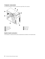
Removing the computer cover, This provides instructions on how to remove the computer cover.
 |
View all Lenovo ThinkCentre A58e manuals
Add to My Manuals
Save this manual to your list of manuals |
Page 73 highlights
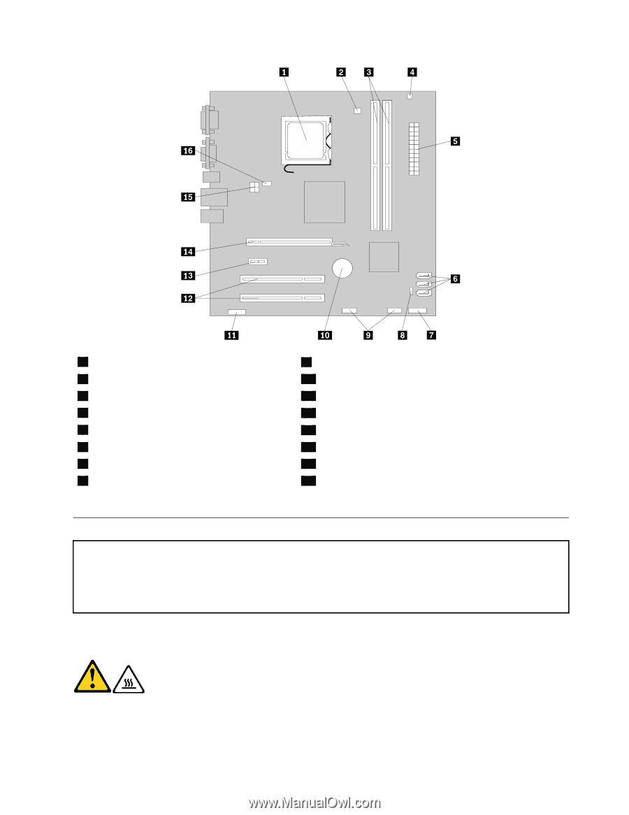
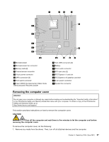
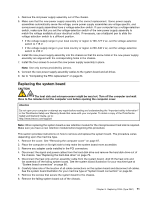
1 Microprocessor 2 Microprocessor fan connector 3 Memory slots (2) 4 Thermal sensor connector 5 24-pin power connector 6 SATA connectors (3) 7 Front panel connector 8 Clear CMOS (Complementary Metal Oxide Semiconductor) /Recovery jumper 9 Front USB connectors (2) 10 Battery 11 Front audio connector 12 PCI card slots (2) 13 PCI Express x1 card slot 14 PCI Express x16 graphics card slot 15 4-pin power connector 16 System fan connector Removing the computer cover Attention Do not open your computer or attempt any repair before reading and understanding the "Important safety information" in the ThinkCentre Safety and Warranty Guide that came with your computer. To obtain a copy of the ThinkCentre Safety and Warranty Guide, go to: http://www.lenovo.com/support This section provides instructions on how to remove the computer cover. CAUTION: Turn off the computer and wait three to five minutes to let the computer cool before removing the computer cover. To remove the computer cover, do the following: 1. Remove any media from the drives. Then, turn off all attached devices and the computer. Chapter 8. Replacing FRUs (Type 0841) 67
-
 1
1 -
2
-
3
-
4
-
5
-
6
-
7
-
8
-
9
-
10
-
11
-
12
-
13
-
14
-
15
-
16
-
17
-
18
-
19
-
20
-
21
-
22
-
23
-
24
-
25
-
26
-
27
-
28
-
29
-
30
-
31
-
32
-
33
-
34
-
35
-
36
-
37
-
38
-
39
-
40
-
41
-
42
-
43
-
44
-
45
-
46
-
47
-
48
-
49
-
50
-
51
-
52
-
53
-
54
-
55
-
56
-
57
-
58
-
59
-
60
-
61
-
62
-
63
-
64
-
65
-
66
-
67
-
 68
68 -
 69
69 -
 70
70 -
 71
71 -
 72
72 -
 73
73 -
 74
74 -
 75
75 -
 76
76 -
 77
77 -
 78
78 -
79
-
80
-
81
-
82
-
83
-
84
-
85
-
86
-
87
-
88
-
89
-
90
-
91
-
92
-
93
-
94
-
95
-
96
-
97
-
98
-
99
-
100
-
101
-
102
-
103
-
104
 |
 |