Lenovo ThinkCentre A58e Hardware Maintenance Manual - Page 78
Install the heat sink and fan assembly on the system board. See Replacing the heat sink and fan
 |
View all Lenovo ThinkCentre A58e manuals
Add to My Manuals
Save this manual to your list of manuals |
Page 78 highlights
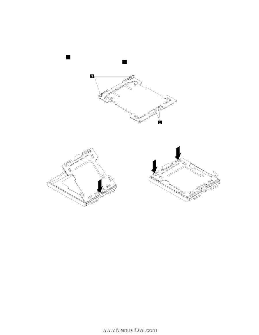
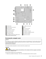
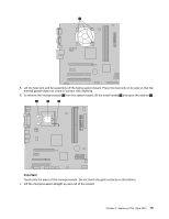
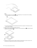
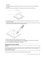
9. The failing system board must be returned with a microprocessor socket cover to protect the pins during shipping and handling. Install the microprocessor socket cover removed from the new system board on the failing system board. To install the microprocessor socket cover: a. Make sure the microprocessor has been removed from the microprocessor socket, and then close the microprocessor retainer and lock it into position with the small handle. b. Insert the tabs 1 of the socket cover into the hinged side of the socket, and then press the other side of the socket cover downward until the tabs 2 snap into position. Figure 5. Tabs on the microprocessor socket cover (bottom view) Figure 6. Installing the microprocessor socket cover 10. Install the new retention module to the new system board. 11. Remove the memory modules from the failing system board and install them in the same location on the new system board. 12. Install the new system board into the chassis and align the screw holes with those in the chassis. Insert and tighten the screws that secure the system board. 13. Install the new Microprocessor in the new system board. See "Replacing the microprocessor" on page 74. 14. Install the heat sink and fan assembly on the system board. See "Replacing the heat sink and fan assembly" on page 73. 15. Connect the heat sink and fan assembly cable to the new system board. See the system board illustration for your machine type at "System board connectors" on page 66. 16. Pivot the hard disk drive back into position. 17. Connect the power and signal cables to the hard disk drive. 18. Connect all cables to the system board. See the system board illustration for your machine type at "System board connectors" on page 66. 72 ThinkCentre Hardware Maintenance Manual
-
 1
1 -
2
-
3
-
4
-
5
-
6
-
7
-
8
-
9
-
10
-
11
-
12
-
13
-
14
-
15
-
16
-
17
-
18
-
19
-
20
-
21
-
22
-
23
-
24
-
25
-
26
-
27
-
28
-
29
-
30
-
31
-
32
-
33
-
34
-
35
-
36
-
37
-
38
-
39
-
40
-
41
-
42
-
43
-
44
-
45
-
46
-
47
-
48
-
49
-
50
-
51
-
52
-
53
-
54
-
55
-
56
-
57
-
58
-
59
-
60
-
61
-
62
-
63
-
64
-
65
-
66
-
67
-
68
-
69
-
70
-
71
-
72
-
 73
73 -
 74
74 -
 75
75 -
 76
76 -
 77
77 -
 78
78 -
 79
79 -
 80
80 -
 81
81 -
 82
82 -
 83
83 -
84
-
85
-
86
-
87
-
88
-
89
-
90
-
91
-
92
-
93
-
94
-
95
-
96
-
97
-
98
-
99
-
100
-
101
-
102
-
103
-
104
 |
 |