Lenovo ThinkCentre A58e Hardware Maintenance Manual - Page 80
Replacing the microprocessor
 |
View all Lenovo ThinkCentre A58e manuals
Add to My Manuals
Save this manual to your list of manuals |
Page 80 highlights
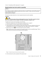
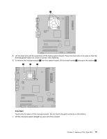
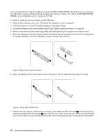
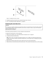
Notes: a. You might have to gently twist the heat sink and fan assembly to free it from the microprocessor. b. When handling the heat sink and fan assembly, do not touch the thermal grease on the bottom of the heat sink and fan assembly. 6. Place the new heat sink and fan assembly on the system board so that the four screws are aligned with the corresponding holes on the system board. Make sure that you place the new heat sink and fan assembly properly so that you can easily connect the heat sink and fan assembly cable to the microprocessor fan connector on the system board. 7. Alternate tightening each screw a small and equal amount until the heat sink and fan assembly is secured to the system board. Do not over-tighten the screws. 8. Connect the new heat sink and fan assembly cable to the microprocessor fan connector on the system board. 9. Go to "Completing the FRU replacement" on page 84. Replacing the microprocessor CAUTION: The heat sink and microprocessor might be very hot. Turn off the computer and wait three to five minutes to let the computer cool before opening the computer cover. Attention Do not open your computer or attempt any repair before reading and understanding the "Important safety information" in the ThinkCentre Safety and Warranty Guide that came with your computer. To obtain a copy of the ThinkCentre Safety and Warranty Guide, go to: http://www.lenovo.com/support This section provides information on how to remove and replace the microprocessor. The procedure varies depending upon the machine type. 1. Remove the computer cover. See "Removing the computer cover" on page 67. 2. Place the computer on its right side to help make the microprocessor more accessible. 3. Disconnect the heat sink and fan assembly cable from the system board. See the system board illustration for your machine type at "System board connectors" on page 66. 4. Remove the four screws 1 securing the heat sink and fan assembly to the system board. See "Replacing the heat sink and fan assembly" on page 73 74 ThinkCentre Hardware Maintenance Manual
-
 1
1 -
2
-
3
-
4
-
5
-
6
-
7
-
8
-
9
-
10
-
11
-
12
-
13
-
14
-
15
-
16
-
17
-
18
-
19
-
20
-
21
-
22
-
23
-
24
-
25
-
26
-
27
-
28
-
29
-
30
-
31
-
32
-
33
-
34
-
35
-
36
-
37
-
38
-
39
-
40
-
41
-
42
-
43
-
44
-
45
-
46
-
47
-
48
-
49
-
50
-
51
-
52
-
53
-
54
-
55
-
56
-
57
-
58
-
59
-
60
-
61
-
62
-
63
-
64
-
65
-
66
-
67
-
68
-
69
-
70
-
71
-
72
-
73
-
74
-
 75
75 -
 76
76 -
 77
77 -
 78
78 -
 79
79 -
 80
80 -
 81
81 -
 82
82 -
 83
83 -
 84
84 -
 85
85 -
86
-
87
-
88
-
89
-
90
-
91
-
92
-
93
-
94
-
95
-
96
-
97
-
98
-
99
-
100
-
101
-
102
-
103
-
104
 |
 |
