Lenovo ThinkCentre M55e Hardware Maintenance Manual - Page 114
Replacing, assembly
 |
View all Lenovo ThinkCentre M55e manuals
Add to My Manuals
Save this manual to your list of manuals |
Page 114 highlights
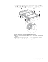
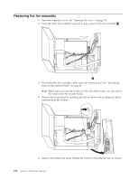
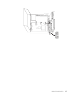
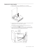
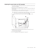
Replacing the fan assembly 1. Open the computer cover. See "Opening the cover" on page 83. 2. Pivot the drive bay assembly upward to gain access to the fan assembly 1 . 3. Disconnect the fan assembly cables from the system board. See "Identifying parts on the system board" on page 85. Note: Make sure you note the location of the fan cables when you disconnect the cables from the system board. 4. Remove the front bezel by releasing the tab as shown and pivoting the bezel outward from the bottom. 5. Remove the plastic fan insert behind the bezel by releasing the tabs as shown. 108 Hardware Maintenance Manual
-
 1
1 -
2
-
3
-
4
-
5
-
6
-
7
-
8
-
9
-
10
-
11
-
12
-
13
-
14
-
15
-
16
-
17
-
18
-
19
-
20
-
21
-
22
-
23
-
24
-
25
-
26
-
27
-
28
-
29
-
30
-
31
-
32
-
33
-
34
-
35
-
36
-
37
-
38
-
39
-
40
-
41
-
42
-
43
-
44
-
45
-
46
-
47
-
48
-
49
-
50
-
51
-
52
-
53
-
54
-
55
-
56
-
57
-
58
-
59
-
60
-
61
-
62
-
63
-
64
-
65
-
66
-
67
-
68
-
69
-
70
-
71
-
72
-
73
-
74
-
75
-
76
-
77
-
78
-
79
-
80
-
81
-
82
-
83
-
84
-
85
-
86
-
87
-
88
-
89
-
90
-
91
-
92
-
93
-
94
-
95
-
96
-
97
-
98
-
99
-
100
-
101
-
102
-
103
-
104
-
105
-
106
-
107
-
108
-
 109
109 -
 110
110 -
 111
111 -
 112
112 -
 113
113 -
 114
114 -
 115
115 -
 116
116 -
 117
117 -
 118
118 -
 119
119 -
120
-
121
-
122
-
123
-
124
-
125
-
126
-
127
-
128
-
129
-
130
-
131
-
132
-
133
-
134
-
135
-
136
-
137
-
138
-
139
-
140
-
141
-
142
-
143
-
144
-
145
-
146
-
147
-
148
-
149
-
150
-
151
-
152
-
153
-
154
-
155
-
156
-
157
-
158
-
159
-
160
-
161
-
162
-
163
-
164
-
165
-
166
-
167
-
168
-
169
-
170
-
171
-
172
-
173
-
174
-
175
-
176
-
177
-
178
-
179
-
180
-
181
-
182
-
183
-
184
-
185
-
186
-
187
-
188
-
189
-
190
-
191
-
192
-
193
-
194
-
195
-
196
-
197
-
198
-
199
-
200
-
201
-
202
-
203
-
204
-
205
-
206
-
207
-
208
-
209
-
210
 |
 |
Replacing
the
fan
assembly
1.
Open
the
computer
cover.
See
“Opening
the
cover”
on
page
83.
2.
Pivot
the
drive
bay
assembly
upward
to
gain
access
to
the
fan
assembly
±1²
.
3.
Disconnect
the
fan
assembly
cables
from
the
system
board.
See
“Identifying
parts
on
the
system
board”
on
page
85.
Note:
Make
sure
you
note
the
location
of
the
fan
cables
when
you
disconnect
the
cables
from
the
system
board.
4.
Remove
the
front
bezel
by
releasing
the
tab
as
shown
and
pivoting
the
bezel
outward
from
the
bottom.
5.
Remove
the
plastic
fan
insert
behind
the
bezel
by
releasing
the
tabs
as
shown.
108
Hardware
Maintenance
Manual