Lenovo ThinkCentre M55e Hardware Maintenance Manual - Page 93
connector.
 |
View all Lenovo ThinkCentre M55e manuals
Add to My Manuals
Save this manual to your list of manuals |
Page 93 highlights
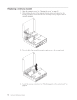
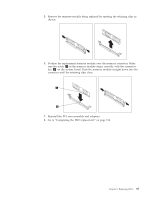
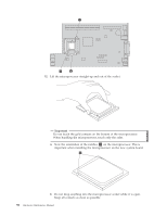
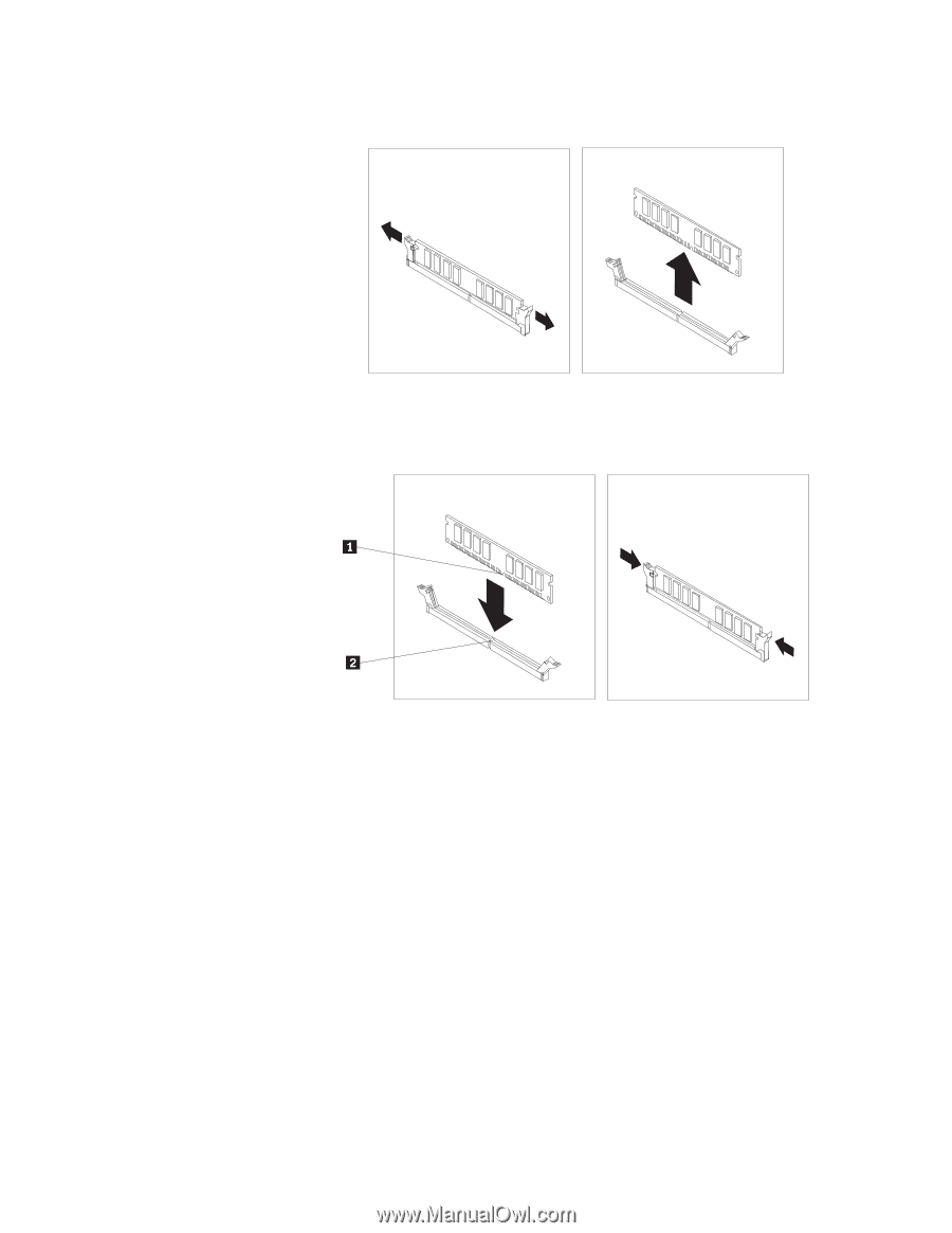
5. Remove the memory module being replaced by opening the retaining clips as shown. 6. Position the replacement memory module over the memory connector. Make sure the notch 1 on the memory module aligns correctly with the connector key 2 on the system board. Push the memory module straight down into the connector until the retaining clips close. 7. Reinstall the PCI riser assembly and adapters. 8. Go to "Completing the FRU replacement" on page 114. Chapter 8. Replacing FRUs 87
-
 1
1 -
2
-
3
-
4
-
5
-
6
-
7
-
8
-
9
-
10
-
11
-
12
-
13
-
14
-
15
-
16
-
17
-
18
-
19
-
20
-
21
-
22
-
23
-
24
-
25
-
26
-
27
-
28
-
29
-
30
-
31
-
32
-
33
-
34
-
35
-
36
-
37
-
38
-
39
-
40
-
41
-
42
-
43
-
44
-
45
-
46
-
47
-
48
-
49
-
50
-
51
-
52
-
53
-
54
-
55
-
56
-
57
-
58
-
59
-
60
-
61
-
62
-
63
-
64
-
65
-
66
-
67
-
68
-
69
-
70
-
71
-
72
-
73
-
74
-
75
-
76
-
77
-
78
-
79
-
80
-
81
-
82
-
83
-
84
-
85
-
86
-
87
-
 88
88 -
 89
89 -
 90
90 -
 91
91 -
 92
92 -
 93
93 -
 94
94 -
 95
95 -
 96
96 -
 97
97 -
 98
98 -
99
-
100
-
101
-
102
-
103
-
104
-
105
-
106
-
107
-
108
-
109
-
110
-
111
-
112
-
113
-
114
-
115
-
116
-
117
-
118
-
119
-
120
-
121
-
122
-
123
-
124
-
125
-
126
-
127
-
128
-
129
-
130
-
131
-
132
-
133
-
134
-
135
-
136
-
137
-
138
-
139
-
140
-
141
-
142
-
143
-
144
-
145
-
146
-
147
-
148
-
149
-
150
-
151
-
152
-
153
-
154
-
155
-
156
-
157
-
158
-
159
-
160
-
161
-
162
-
163
-
164
-
165
-
166
-
167
-
168
-
169
-
170
-
171
-
172
-
173
-
174
-
175
-
176
-
177
-
178
-
179
-
180
-
181
-
182
-
183
-
184
-
185
-
186
-
187
-
188
-
189
-
190
-
191
-
192
-
193
-
194
-
195
-
196
-
197
-
198
-
199
-
200
-
201
-
202
-
203
-
204
-
205
-
206
-
207
-
208
-
209
-
210
 |
 |
5.
Remove
the
memory
module
being
replaced
by
opening
the
retaining
clips
as
shown.
6.
Position
the
replacement
memory
module
over
the
memory
connector.
Make
sure
the
notch
±1²
on
the
memory
module
aligns
correctly
with
the
connector
key
±2²
on
the
system
board.
Push
the
memory
module
straight
down
into
the
connector
until
the
retaining
clips
close.
7.
Reinstall
the
PCI
riser
assembly
and
adapters.
8.
Go
to
“Completing
the
FRU
replacement”
on
page
114.
Chapter
8.
Replacing
FRUs
87