Lenovo ThinkCentre M55e Hardware Maintenance Manual - Page 95
connectors
 |
View all Lenovo ThinkCentre M55e manuals
Add to My Manuals
Save this manual to your list of manuals |
Page 95 highlights
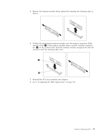
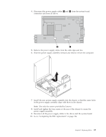
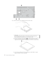
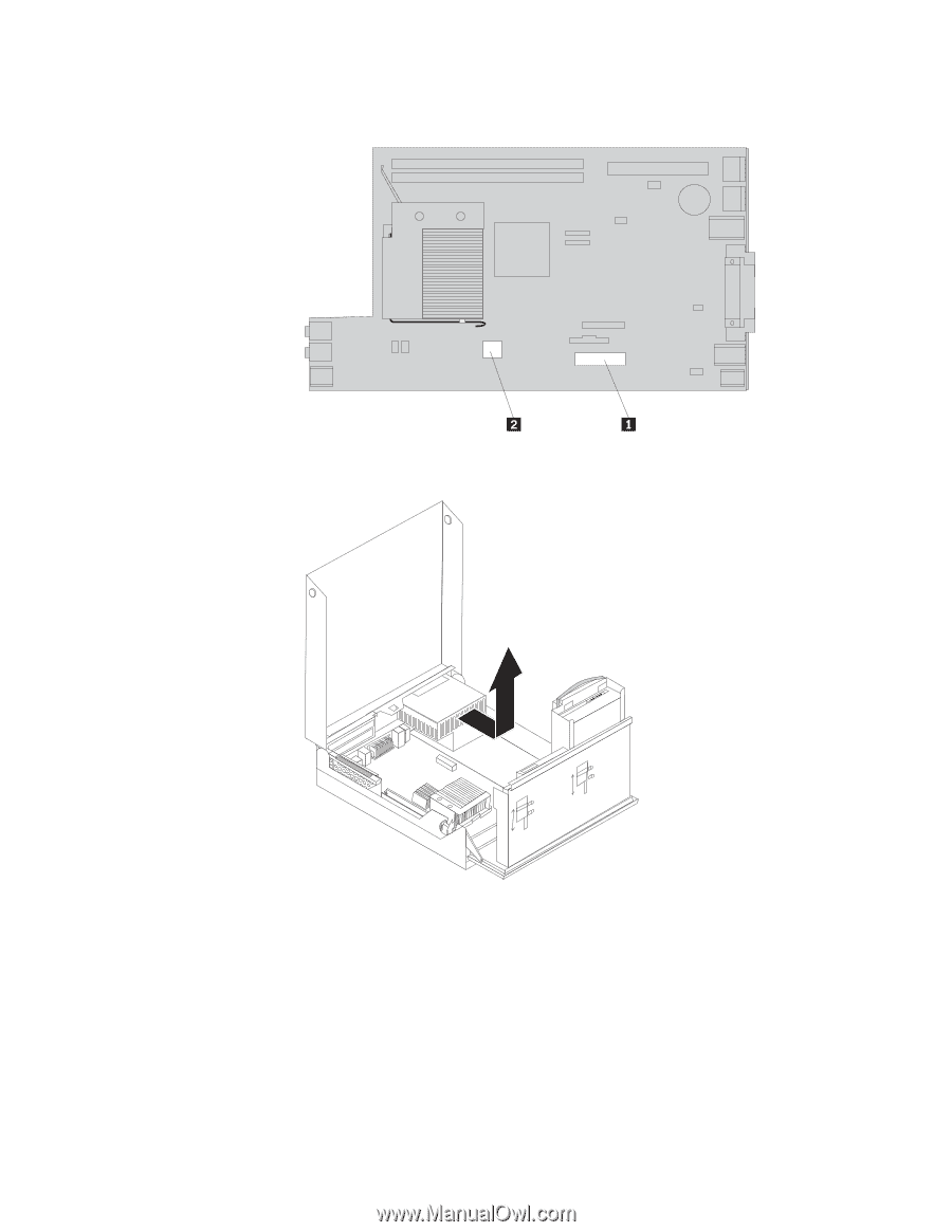
4. Disconnect the power supply cables 1 and 2 from the system board connectors and from all drives. 5. Remove the power supply cables from the cable clips and ties. 6. Slide the power supply assembly forward and remove it from the computer. 7. Install the new power supply assembly into the chassis so that the screw holes in the power supply assembly align with those in the chassis. Note: Use only the screws provided by Lenovo. 8. Install and tighten the four screws at the rear of the chassis to secure the power supply assembly. 9. Reconnect all the power supply cables to the drives and the system board. 10. Go to "Completing the FRU replacement" on page 114. Chapter 8. Replacing FRUs 89
-
 1
1 -
2
-
3
-
4
-
5
-
6
-
7
-
8
-
9
-
10
-
11
-
12
-
13
-
14
-
15
-
16
-
17
-
18
-
19
-
20
-
21
-
22
-
23
-
24
-
25
-
26
-
27
-
28
-
29
-
30
-
31
-
32
-
33
-
34
-
35
-
36
-
37
-
38
-
39
-
40
-
41
-
42
-
43
-
44
-
45
-
46
-
47
-
48
-
49
-
50
-
51
-
52
-
53
-
54
-
55
-
56
-
57
-
58
-
59
-
60
-
61
-
62
-
63
-
64
-
65
-
66
-
67
-
68
-
69
-
70
-
71
-
72
-
73
-
74
-
75
-
76
-
77
-
78
-
79
-
80
-
81
-
82
-
83
-
84
-
85
-
86
-
87
-
88
-
89
-
 90
90 -
 91
91 -
 92
92 -
 93
93 -
 94
94 -
 95
95 -
 96
96 -
 97
97 -
 98
98 -
 99
99 -
 100
100 -
101
-
102
-
103
-
104
-
105
-
106
-
107
-
108
-
109
-
110
-
111
-
112
-
113
-
114
-
115
-
116
-
117
-
118
-
119
-
120
-
121
-
122
-
123
-
124
-
125
-
126
-
127
-
128
-
129
-
130
-
131
-
132
-
133
-
134
-
135
-
136
-
137
-
138
-
139
-
140
-
141
-
142
-
143
-
144
-
145
-
146
-
147
-
148
-
149
-
150
-
151
-
152
-
153
-
154
-
155
-
156
-
157
-
158
-
159
-
160
-
161
-
162
-
163
-
164
-
165
-
166
-
167
-
168
-
169
-
170
-
171
-
172
-
173
-
174
-
175
-
176
-
177
-
178
-
179
-
180
-
181
-
182
-
183
-
184
-
185
-
186
-
187
-
188
-
189
-
190
-
191
-
192
-
193
-
194
-
195
-
196
-
197
-
198
-
199
-
200
-
201
-
202
-
203
-
204
-
205
-
206
-
207
-
208
-
209
-
210
 |
 |
4.
Disconnect
the
power
supply
cables
±1²
and
±2²
from
the
system
board
connectors
and
from
all
drives.
5.
Remove
the
power
supply
cables
from
the
cable
clips
and
ties.
6.
Slide
the
power
supply
assembly
forward
and
remove
it
from
the
computer.
7.
Install
the
new
power
supply
assembly
into
the
chassis
so
that
the
screw
holes
in
the
power
supply
assembly
align
with
those
in
the
chassis.
Note:
Use
only
the
screws
provided
by
Lenovo.
8.
Install
and
tighten
the
four
screws
at
the
rear
of
the
chassis
to
secure
the
power
supply
assembly.
9.
Reconnect
all
the
power
supply
cables
to
the
drives
and
the
system
board.
10.
Go
to
“Completing
the
FRU
replacement”
on
page
114.
Chapter
8.
Replacing
FRUs
89