Lenovo ThinkCentre M55e Hardware Maintenance Manual - Page 99
microprocessor
 |
View all Lenovo ThinkCentre M55e manuals
Add to My Manuals
Save this manual to your list of manuals |
Page 99 highlights
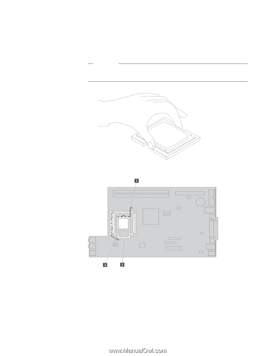
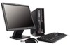
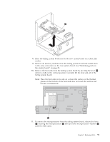
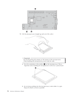
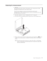
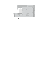
13. On the new system board, release the lever securing the microprocessor retainer and then pivot the retainer until it is fully open. 14. Position the microprocessor so that the notches on the microprocessor are aligned with the tabs in the microprocessor socket on the new system board. Important To avoid damaging the microprocessor, do not tilt the microprocessor when installing it into the microprocessor socket. 15. Lower the microprocessor straight down into the microprocessor socket. 16. Lower the microprocessor retainer 2 and then lower the lever 1 to secure the retainer. Make sure the lever is securely locked into position. Note: There will be a black plastic cover on the microprocessor retainer to protect the socket on the new system board. Remove the black plastic cover as you lock the microprocessor in position. Place the black plastic cover on the microprocessor retainer of the failing system board. 17. Place the heat sink into position and lower the lever to secure the heat sink. 18. To install the new system board, tilt the front end of the system board between the diskette drive and the fan assembly, and position it so that the slots in the new system board are aligned with the pins in the chassis. Chapter 8. Replacing FRUs 93
-
 1
1 -
2
-
3
-
4
-
5
-
6
-
7
-
8
-
9
-
10
-
11
-
12
-
13
-
14
-
15
-
16
-
17
-
18
-
19
-
20
-
21
-
22
-
23
-
24
-
25
-
26
-
27
-
28
-
29
-
30
-
31
-
32
-
33
-
34
-
35
-
36
-
37
-
38
-
39
-
40
-
41
-
42
-
43
-
44
-
45
-
46
-
47
-
48
-
49
-
50
-
51
-
52
-
53
-
54
-
55
-
56
-
57
-
58
-
59
-
60
-
61
-
62
-
63
-
64
-
65
-
66
-
67
-
68
-
69
-
70
-
71
-
72
-
73
-
74
-
75
-
76
-
77
-
78
-
79
-
80
-
81
-
82
-
83
-
84
-
85
-
86
-
87
-
88
-
89
-
90
-
91
-
92
-
93
-
 94
94 -
 95
95 -
 96
96 -
 97
97 -
 98
98 -
 99
99 -
 100
100 -
 101
101 -
 102
102 -
 103
103 -
 104
104 -
105
-
106
-
107
-
108
-
109
-
110
-
111
-
112
-
113
-
114
-
115
-
116
-
117
-
118
-
119
-
120
-
121
-
122
-
123
-
124
-
125
-
126
-
127
-
128
-
129
-
130
-
131
-
132
-
133
-
134
-
135
-
136
-
137
-
138
-
139
-
140
-
141
-
142
-
143
-
144
-
145
-
146
-
147
-
148
-
149
-
150
-
151
-
152
-
153
-
154
-
155
-
156
-
157
-
158
-
159
-
160
-
161
-
162
-
163
-
164
-
165
-
166
-
167
-
168
-
169
-
170
-
171
-
172
-
173
-
174
-
175
-
176
-
177
-
178
-
179
-
180
-
181
-
182
-
183
-
184
-
185
-
186
-
187
-
188
-
189
-
190
-
191
-
192
-
193
-
194
-
195
-
196
-
197
-
198
-
199
-
200
-
201
-
202
-
203
-
204
-
205
-
206
-
207
-
208
-
209
-
210
 |
 |