Lenovo ThinkCentre M55e Hardware Maintenance Manual - Page 77
Utility
 |
View all Lenovo ThinkCentre M55e manuals
Add to My Manuals
Save this manual to your list of manuals |
Page 77 highlights
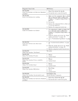
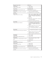
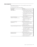
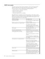
Diagnostic Error Code 170-0XX-XXX Voltage Sensor(s) failure 170-195-XXX Voltage Sensor(s) Test aborted by user 170-196-XXX Voltage Sensor(s) test halt error threshold exceeded 170-197-XXX Voltage Sensor(s) test warning 170-198-XXX Voltage Sensor(s) test aborted 170-199-XXX Voltage Sensor(s) test failed cause unknown 170-250-XXX 170-251-XXX Voltage Sensor(s) Voltage limit error 170-254-XXX Voltage Sensor(s) Voltage Regulator Module error 175-000-XXX Thermal Sensor(s) Test Passed 175-0XX-XXX Thermal Sensor(s) failure 175-195-XXX Thermal Sensor(s) Test aborted by user 175-196-XXX Thermal Sensor(s) test halt error threshold exceeded FRU/Action 1. Flash system 2. System board Information only Re-start the test if necessary 1. Press F3 to review the log file 2. Re-start the test to reset the log file 1. Make sure the component that is called out is connected and/or enabled. See Chapter 6, "Using the Setup Utility," on page 49 2. Re-run test 3. Replace the component that is called out in warning statement 4. Replace the component under test 1. If a component is called out make sure it is connected and/or enabled. See Chapter 6, "Using the Setup Utility," on page 49 2. Flash the system and re-test. See "Flash update procedures" on page 197 3. Go to "Undetermined problems" on page 79 1. See "Undetermined problems" on page 79 2. Flash the system and re-test. See "Flash update procedures" on page 197 3. Replace component under function test 1. Power supply 2. System board 1. Voltage Regulator Module (VRM) 2. Microprocessor 3. System board No action 1. Flash system 2. System board Information only Re-start the test if necessary 1. Press F3 to review the log file 2. Re-start the test to reset the log file Chapter 7. Symptom-to-FRU Index 71
-
 1
1 -
2
-
3
-
4
-
5
-
6
-
7
-
8
-
9
-
10
-
11
-
12
-
13
-
14
-
15
-
16
-
17
-
18
-
19
-
20
-
21
-
22
-
23
-
24
-
25
-
26
-
27
-
28
-
29
-
30
-
31
-
32
-
33
-
34
-
35
-
36
-
37
-
38
-
39
-
40
-
41
-
42
-
43
-
44
-
45
-
46
-
47
-
48
-
49
-
50
-
51
-
52
-
53
-
54
-
55
-
56
-
57
-
58
-
59
-
60
-
61
-
62
-
63
-
64
-
65
-
66
-
67
-
68
-
69
-
70
-
71
-
 72
72 -
 73
73 -
 74
74 -
 75
75 -
 76
76 -
 77
77 -
 78
78 -
 79
79 -
 80
80 -
 81
81 -
 82
82 -
83
-
84
-
85
-
86
-
87
-
88
-
89
-
90
-
91
-
92
-
93
-
94
-
95
-
96
-
97
-
98
-
99
-
100
-
101
-
102
-
103
-
104
-
105
-
106
-
107
-
108
-
109
-
110
-
111
-
112
-
113
-
114
-
115
-
116
-
117
-
118
-
119
-
120
-
121
-
122
-
123
-
124
-
125
-
126
-
127
-
128
-
129
-
130
-
131
-
132
-
133
-
134
-
135
-
136
-
137
-
138
-
139
-
140
-
141
-
142
-
143
-
144
-
145
-
146
-
147
-
148
-
149
-
150
-
151
-
152
-
153
-
154
-
155
-
156
-
157
-
158
-
159
-
160
-
161
-
162
-
163
-
164
-
165
-
166
-
167
-
168
-
169
-
170
-
171
-
172
-
173
-
174
-
175
-
176
-
177
-
178
-
179
-
180
-
181
-
182
-
183
-
184
-
185
-
186
-
187
-
188
-
189
-
190
-
191
-
192
-
193
-
194
-
195
-
196
-
197
-
198
-
199
-
200
-
201
-
202
-
203
-
204
-
205
-
206
-
207
-
208
-
209
-
210
 |
 |