Maytag MGDB700VQ Use and Care Guide - Page 8
Warni - appliances
 |
UPC - 883049140582
View all Maytag MGDB700VQ manuals
Add to My Manuals
Save this manual to your list of manuals |
Page 8 highlights
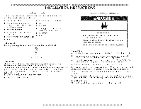
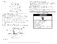
-_/_$11 approved aluminum or copper tubing is acceptable for lengths under 20 ft (6.1 m) if local codes and gas supplier permit. If you are using Natural gas, do not use copper tubing. 4/8" flare x 3/8" NPT adapter fitting between dryer pipe and 3/8" approved tubing. I.engths over 20 ft (6.1 m) should use larger tubing and a different size adapter fitting. If your dryer has been converted to use I.P gas, 4/8" I.P compatible copper tubing can be used. If the total length of the supply line is more than 20 ft (6.1 m), use larger pipe. NOTE: Pipe-joint compounds TEFI.ON ,_t tape. Must include a shutoff valve: that resist the action of I.P gas must be used. Do not use In the U.S.A.: An individual manual shutoff valve must be installed within six (6) feet (1.8 m) of the dryer in accordance with the National Fuel Gas Code, ANSI Z223.1. In Canada: An individual manual shutoff valve must be installed in accordance with the B149.1, Natural Gas and Propane Installation Code. It is recommended that an individual manual shutoff valve be installed within six (6) feet (1.8 m) of the dryer. The location should be easy to reach for opening and closing. A O E Burner Input Requirements: Elevations above 10,000 ft (3,048 m): • When installed above 10,000 ft (3,048 m) a 4% reduction of the burner Btu rating shown on the model/serial number plate is required for each 1,000 ft (305 m) increase in elevation. Gas Supply Pressure Testing • The dryer must be disconnected at pressures greater than _/_psi. from the gas supply piping system during pressure testing Dryer Gas Pipe The gas pipe that comes out through the rear of your dryer has a 3/sll male pipe thread. (5.12cm) (1.9 cm) A. _/s" NPT dryer pipe B D A. _/_" flexible gas connector B. _/s" pipe to flare adapter fitting C. J/_" NPT minimum plugged tapping D. J/_" NPT gas supply line E. Gas shutoff valve Gas supply connection requirements Use an elbow and a _/s II flare x 3/811 NPT adapter fitting between the flexible gas connector and the dryer gas pipe, as needed to avoid kinking. Use only pipe-joint compound. I)o not use TEFI.ON "_*tape. This dryer must be connected to the gas supply line with a listed flexible gas connector that complies with the standard for connectors for gas appliances, ANSI Z21.24 or CSA 6.10. t®TEF[ ON is a registered trademark of E.[. Du Pont De Nemours and Company. 8 Fire Hazard Use a heavy metal vent. Do not use a plastic vent. Do not use a metal foil vent. Failure to follow these instructions or fire. can result in death WARNi NG: To reduce the risk of fire, this dryer MUST BE EXHAUSTEI) OUTI)OORS. IMPORTANT: Observe all governing codes and ordinances. The dryer exhaust must not be connected into any gas vent, chimney, wall, ceiling, or a concealed space of a building.
-
 1
1 -
2
-
 3
3 -
 4
4 -
 5
5 -
 6
6 -
 7
7 -
 8
8 -
 9
9 -
 10
10 -
 11
11 -
 12
12 -
 13
13 -
14
-
15
-
16
-
17
-
18
-
19
-
20
-
21
-
22
-
23
-
24
-
25
-
26
-
27
-
28
-
29
-
30
-
31
-
32
-
33
-
34
-
35
-
36
-
37
-
38
-
39
-
40
-
41
-
42
-
43
-
44
-
45
-
46
-
47
-
48
-
49
-
50
-
51
-
52
-
53
-
54
-
55
-
56
 |
 |
