McAfee IIP-M65K-ISAA Product Manual - Page 12
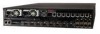
Front panel LEDs, Eight 10 Gigabit small form-factor pluggable XFP 10 Gigabit Monitoring ports
 |
View all McAfee IIP-M65K-ISAA manuals
Add to My Manuals
Save this manual to your list of manuals |
Page 12 highlights
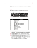
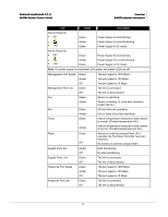
McAfee® IntruShield® IPS 4.1 M-6050 Sensor Product Guide Overview M-6050 physical description 5 Eight 10 Gigabit small form-factor pluggable (XFP) 10 Gigabit Monitoring ports, which enable you to monitor eight SPAN ports, four full-duplex tapped segments, four segments in-line, or a combination (that is, two full-duplex segment, four SPAN ports). The Monitoring interfaces of the M-6050 work in stealth mode, meaning they have no IP address and are not visible on the monitored segment. If you choose to run in failover mode, port 4A is used to interconnect with a standby sensor. Note: The gigabit ports of the M-6050 running in In-line Mode fail closed, meaning that if the sensor fails, it will interrupt/block data flow. Fail-open functionality requires either the Layer 2 Passthru feature, described in detail in the Sensor Configuration Guide-using ISM or the hardware Gigabit Fail-Open Bypass kit for Gigabit ports, described in Cabling the failover interconnection ports section. 6 One RJ-45 Response port, which, when you're operating in SPAN or TAP mode, enables you to inject response packets back through a switch or router. 7 Eight RJ-11 Fail-Open Control ports, designed for use with the Optical Fail-Open Bypass kit. The ports are marked X1, X2, X3, X4, X5, X6, X7, and X8 and are used in conjunction with ports 1A/1B, 2A/2B, 3A/3B, 4A/4B, 5A/5B, 6A/6B, 7A/7B, and 8A/8B, respectively. 8 One External Compact Flash port. This port is used for two purposes. It is used to control optional fail-open hardware as described in the Gigabit Optical Fail-Open Bypass Kit Quick Guide. It is also used in troubleshooting situations where the sensor's internal flash is corrupted and you must reboot the sensor using the external compact flash. For more information, see the on-line KnowledgeBase at https://mysupport.mcafee.com. 9 Power Supply A (included). Power supply A is included with each sensor. The supply uses a standard IEC port (IEC320-C13). The supply uses a standard IEC port (IEC320-C13). McAfee provides a standard, 2m NEMA 5-15P (US) power cable (3 wire). International customers must procure a country-appropriate power cable. 10 Power Supply B (optional, purchased separately). Power supply B is a hotswappable, redundant power supply. This power supply also uses a standard IEC320-C13 port, and you can use the McAfee-provided cable or acquire one that meets your specific needs. The M-6050 does not have internal taps; it must be used with a third-party external tap to run in tapped mode. Front panel LEDs The front panel LEDs provide status information for the health of the sensor and the activity on its ports. Table 1-1 describes the M-6050 front panel LEDs. 4
-
 1
1 -
2
-
3
-
4
-
5
-
6
-
 7
7 -
 8
8 -
 9
9 -
 10
10 -
 11
11 -
 12
12 -
 13
13 -
 14
14 -
 15
15 -
 16
16 -
 17
17 -
18
-
19
-
20
-
21
-
22
-
23
-
24
-
25
-
26
-
27
-
28
-
29
-
30
-
31
-
32
-
33
-
34
-
35
 |
 |