McAfee IIP-M65K-ISAA Product Manual - Page 19
Mounting a sensor in a rack, Removing a sensor from the rack, M-6050 Quick Start, Guide.
 |
View all McAfee IIP-M65K-ISAA manuals
Add to My Manuals
Save this manual to your list of manuals |
Page 19 highlights
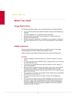
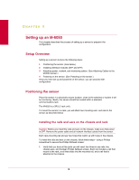
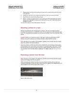
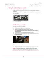
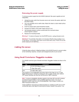
McAfee® IntruShield® IPS 4.1 M-6050 Sensor Product Guide Setting up an M-6050 Positioning the sensor 2 Disassemble the slide rail by pulling the inner rail out and pushing the side latch in to separate. 3 Attach the inner rail to the chassis by fastening it with the screws provided. 4 Attach the ear to each side of the chassis. 5 Mount L-shape and external rail to your rack frame. The adjustable end of the Lshape rail is intended for placement at the back of your rack. Adjust the rail as needed for length. You are now ready to mount the sensor in the rack. Mounting a sensor in a rack McAfee recommends rack-mounting your sensors. The rack-mounting hardware included with the sensors is suitable for most 19-inch equipment racks and telco-type racks. For maintenance purposes, you should have access to the front and rear of the sensor. Caution: Before you mount the sensor in the rack, make sure that power is OFF. Remove the power cable and all network interface cables from the sensor Note: Because of the weight of the appliance, McAfee recommends that two people place the chassis into the rail cabinet. Insert the chassis into the rail cabinet and complete the rack-mounting of the sensor by securing the rack mount ears to two posts or mounting strips in the rack. The ears secure the sensor to two rack posts. Ensure to fasten the ears securely to the rack. You can also mid-mount the Sensor (optional). For details, refer to M-6050 Quick Start Guide. Removing a sensor from the rack Note: Because of the weight of the appliance, McAfee recommends that two people remove the chassis from the rail cabinet. When removing the chassis from the rack, pull chassis forward until you hear the innermost rails snap in place. On each side of the rails, press in the release button as pictured below and continue pulling the chassis. Figure 3: Rail release latch 11
-
 1
1 -
2
-
3
-
4
-
5
-
6
-
7
-
8
-
9
-
10
-
11
-
12
-
13
-
 14
14 -
 15
15 -
 16
16 -
 17
17 -
 18
18 -
 19
19 -
 20
20 -
 21
21 -
 22
22 -
 23
23 -
 24
24 -
25
-
26
-
27
-
28
-
29
-
30
-
31
-
32
-
33
-
34
-
35
 |
 |