McAfee IIP-M65K-ISAA Product Manual - Page 26
Cabling the Response port, ► To connect the Response port to a network device:
 |
View all McAfee IIP-M65K-ISAA manuals
Add to My Manuals
Save this manual to your list of manuals |
Page 26 highlights
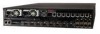
McAfee® IntruShield® IPS 4.1 M-6050 Sensor Product Guide Name Baud rate Number of bits Parity Stop bits Flow Control Setting 38400 8 None 1 None Attaching Cables to the M-6050 Cabling the Response port Cabling the Response port The sensors' Response ports are used to send responses to attacks; when operating in TAP or SPAN mode, for example, you cannot inject response packets via a tap. You must use a Response port. ► To connect the Response port to a network device: 1 Plug a Cat-5e Ethernet cable into the Response port (labeled Rx on the sensor front panel). 2 Connect the other end of the cable to the network device (for example, hub, switch, router) through which you want to respond to attacks. Cabling the Fail-Open port Fail-open functionality for the GE Monitoring ports is accomplished using the standard Gigabit Fail-open Bypass Kit, sold separately. (Both Copper and Optical versions are available.) Fail-open functionality for the 10 Gigabit Monitoring ports is accomplished using the standard 10 Gigabit (Optical) Fail-open Bypass Kit, sold separately. For more information, see the documentation that accompanies the Kit. Cabling the Management port The Management (Mgmt) port is used for communication with the Manager server. ► To connect the sensor to the Manager server: 1 Plug a Cat-5e Ethernet cable into the Management port (labeled Mgmt on the sensor front panel). 18
-
 1
1 -
2
-
3
-
4
-
5
-
6
-
7
-
8
-
9
-
10
-
11
-
12
-
13
-
14
-
15
-
16
-
17
-
18
-
19
-
20
-
 21
21 -
 22
22 -
 23
23 -
 24
24 -
 25
25 -
 26
26 -
 27
27 -
 28
28 -
 29
29 -
 30
30 -
 31
31 -
32
-
33
-
34
-
35
 |
 |