McAfee IIP-M65K-ISAA Product Manual - Page 18
Setting up an M-6050, Setup Overview, Positioning the sensor
 |
View all McAfee IIP-M65K-ISAA manuals
Add to My Manuals
Save this manual to your list of manuals |
Page 18 highlights
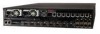
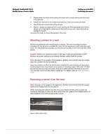
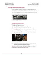
CHAPTER 3 Setting up an M-6050 This chapter describes the process of setting up a sensor to prepare it for configuration. Setup Overview Setting up a sensor involves the following steps: 1 Positioning the sensor. (See below.) 2 Installing interface modules (SFP and XFP). 3 Attaching power, network, and monitoring cables. (See Attaching Cables to the M-6050 sensor.) 4 Powering on the sensor. (See Powering on the sensor.) Once you have set up and powered on the sensor, you can proceed with configuration. Positioning the sensor Place the sensor in a physically secure location, close to the switches or routers it will be monitoring. Ideally, the sensor should be located within a standard communications rack. The M-6050 is a 2RU (2 rack unit). To mount the sensor in a rack, you will attach two mounting ears and rails to the sensor as described below. Installing the rails and ears on the chassis and rack Caution: Before you install the rails and ears on the chassis, make sure that power is OFF. Remove the power cable and all network interface cables from the sensor. Each rack-mounting rail and ear has holes that match up with holes in the chassis. To install the rails and ears on the chassis, follow these steps-using a Phillips screwdriver to secure the Phillips flathead screws: 1 Verify that you have all the parts you will need: two three-in-one rails, two chassis ears, and fourteen Phillips flathead screws. Each rail includes a rail that mount to the rack, a rail that slides into the mounted rail, and a rail that is attached to the chassis. 10
-
 1
1 -
2
-
3
-
4
-
5
-
6
-
7
-
8
-
9
-
10
-
11
-
12
-
 13
13 -
 14
14 -
 15
15 -
 16
16 -
 17
17 -
 18
18 -
 19
19 -
 20
20 -
 21
21 -
 22
22 -
 23
23 -
24
-
25
-
26
-
27
-
28
-
29
-
30
-
31
-
32
-
33
-
34
-
35
 |
 |