McAfee IIP-M65K-ISAA Product Manual - Page 30
Using Fail-Open hardware, Caution 1
 |
View all McAfee IIP-M65K-ISAA manuals
Add to My Manuals
Save this manual to your list of manuals |
Page 30 highlights
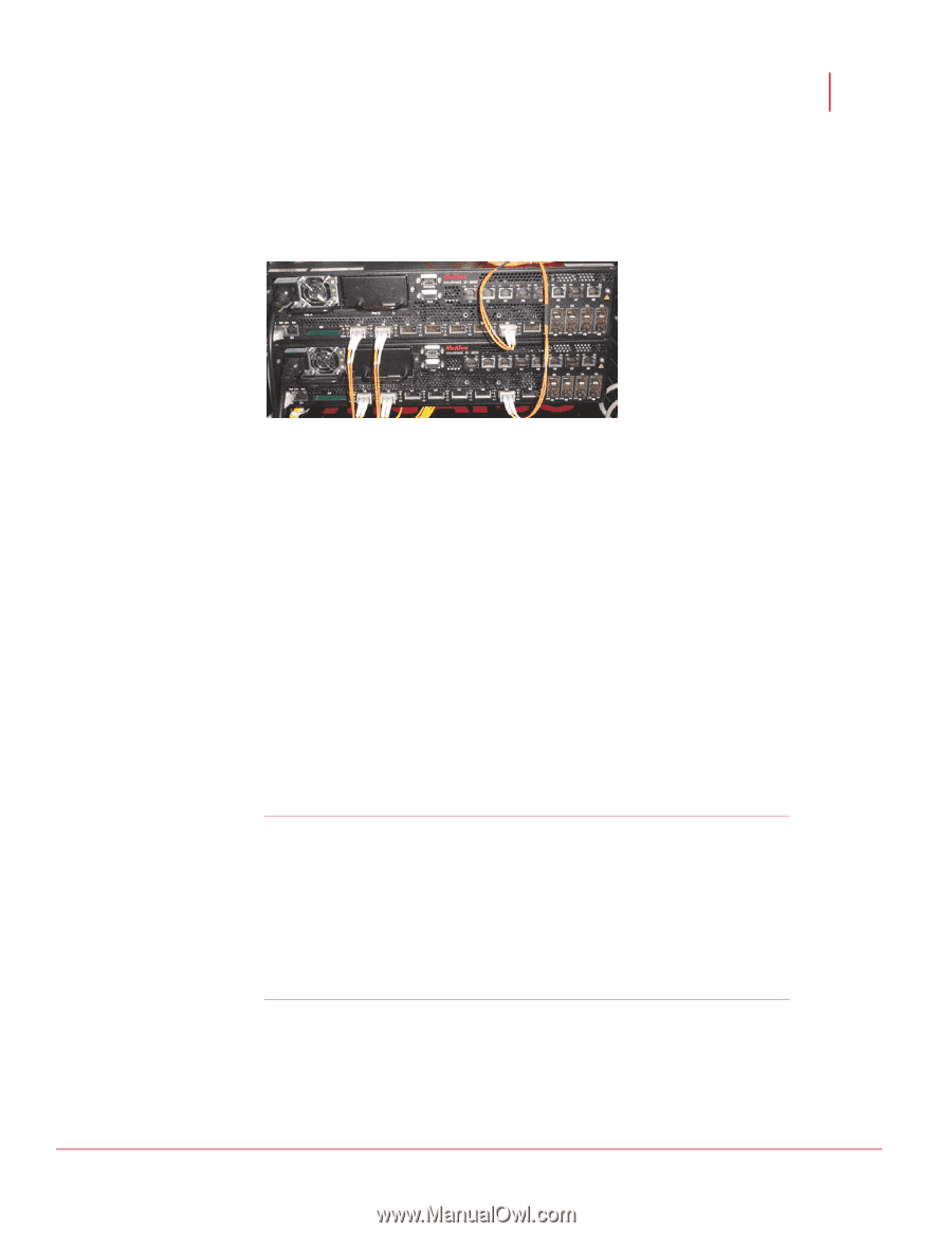
McAfee® IntruShield® IPS 4.1 M-6050 Sensor Product Guide Attaching Cables to the M-6050 Using Fail-Open hardware To connect two M-6050s for failover: 1 Plug the cable appropriate for use with your XFP module into port 4A of the active sensor. 2 Connect the other end of the cable to port 4A of the standby sensor. Figure 10: Cabling M-6050 sensors for Failover Using Fail-Open hardware The standard Gigabit Fail-Open Kit and the 10 Gigabit Fail-Open Kit (sold separately) minimizes the potential risks of in-line IntruShield sensor failure on critical network links. Both Copper and Optical versions of the Kit are available for 1 Gigabit ports. A 10 Gigabit Optical Kit is also available for the 10 Gigabit ports. The Monitoring ports on IntruShield sensors fail closed; thus, if the sensor is deployed in-line, a hardware failure results in network downtime. Fail-open operation for the Monitoring ports requires the use of the optional external Bypass Switch provided in the Kit. With the Bypass Switch in place, normal sensor operation supplies power to the switch via a control cable. While the sensor is operating, the switch is "on" and routes all traffic directly through the sensor. When the sensor fails, the switch automatically shifts to a bypass state: in-line traffic continues to flow through the network link, but is no longer routed through the sensor. Once the sensor resumes normal operation, the switch returns to the "on" state, once again enabling in-line monitoring. Caution 1: Note that sensor outage breaks the link connecting the devices on either side of the sensor for a brief moment and requires the renegotiation of the network link between the two peer devices connected to the sensor. Depending on the network equipment, this disruption introduced by the renegotiation of the link layer between the two peer devices may range from a couple of seconds to more than a minute with certain vendors' devices. Caution 2: A very brief link disruption may also occur while the links between the sensor and each of the peer devices are renegotiated to place the sensor back in in-line mode. This outage, again, varies depending on the device, and can range from a few seconds to more than a minute. Installation and troubleshooting instructions for the Kit can be found in the Quick Guide that accompanies the kit. For example, for more information on the Optical kit, see the standard Gigabit Optical Fail-Open Bypass Kit Guide. 22
-
 1
1 -
2
-
3
-
4
-
5
-
6
-
7
-
8
-
9
-
10
-
11
-
12
-
13
-
14
-
15
-
16
-
17
-
18
-
19
-
20
-
21
-
22
-
23
-
24
-
 25
25 -
 26
26 -
 27
27 -
 28
28 -
 29
29 -
 30
30 -
 31
31 -
 32
32 -
 33
33 -
 34
34 -
 35
35
 |
 |