McAfee IIP-M65K-ISAA Product Manual - Page 28
Default monitoring port speed settings, Cable types for routers, switches, hubs, and PCs
 |
View all McAfee IIP-M65K-ISAA manuals
Add to My Manuals
Save this manual to your list of manuals |
Page 28 highlights
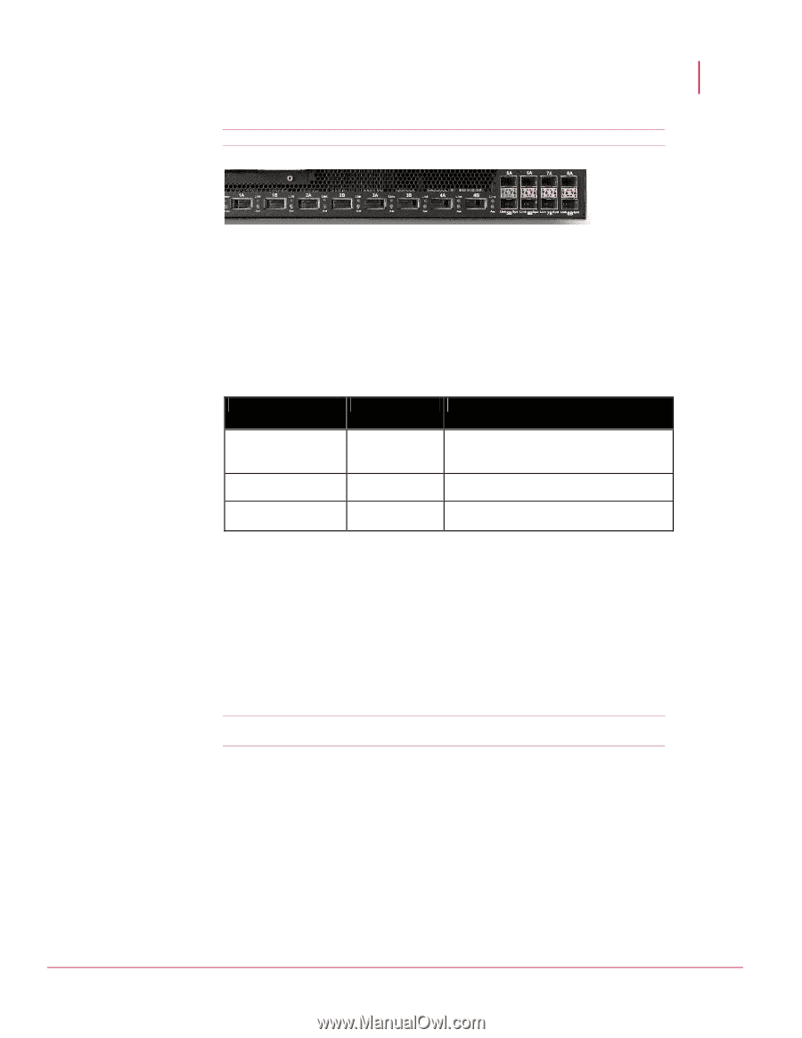
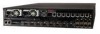
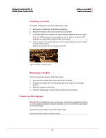
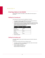
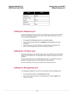
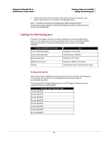
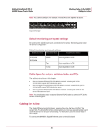
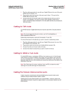
McAfee® IntruShield® IPS 4.1 M-6050 Sensor Product Guide Attaching Cables to the M-6050 Cabling for in-line Note: You cannot configure, for example, IA and 2A to work together as a pair. Figure 9: Port pair Default monitoring port speed settings Be sure that the switch/router ports connected to the sensor Monitoring ports match the sensor configuration. Default monitoring port speed settings Monitoring Ports Operating Mode Speed/Duplex Setting XFP ports SFP ports SPAN Tap In-line Auto-negotiation is ON Auto-negotiation is ON Auto-negotiation is ON Cable types for routers, switches, hubs, and PCs The cabling instructions in this chapter • Use a crossover Ethernet RJ-45 cable to connect a router port to the 10/100/1000 copper SFP Monitoring ports. • Use a straight-through Ethernet RJ-45 cable to connect a switch/hub port to 10/100/1000 copper SFP Monitoring ports. • Use a crossover Ethernet RJ-45 cable to connect a router port to PC to the sensor Management port. Note: You should also use a crossover Ethernet RJ-45 cable to connect a PC to the sensor monitoring port. Cabling for in-line The Gigabit Ethernet ports fail closed, meaning they stop the flow of traffic if the sensor fails. To allow traffic to flow uninterrupted, you must use special hardware and cable the sensor for fail-open functionality. For instructions, see the section later in this chapter. To connect the M-6050's Gigabit Ethernet ports so they fail closed: 20
-
 1
1 -
2
-
3
-
4
-
5
-
6
-
7
-
8
-
9
-
10
-
11
-
12
-
13
-
14
-
15
-
16
-
17
-
18
-
19
-
20
-
21
-
22
-
 23
23 -
 24
24 -
 25
25 -
 26
26 -
 27
27 -
 28
28 -
 29
29 -
 30
30 -
 31
31 -
 32
32 -
 33
33 -
34
-
35
 |
 |