McAfee IIP-M65K-ISAA Product Manual - Page 27
Cabling the Monitoring port, Using peer ports
 |
View all McAfee IIP-M65K-ISAA manuals
Add to My Manuals
Save this manual to your list of manuals |
Page 27 highlights
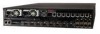
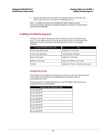
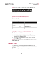
McAfee® IntruShield® IPS 4.1 M-6050 Sensor Product Guide Attaching Cables to the M-6050 Cabling the Monitoring port 2 Connect the other end of the cable to the network device (for example, hub, switch, router) that in turn connects to the Manager server. Note: To isolate and protect your management traffic, McAfee strongly recommends using a separate, dedicated management subnet to interconnect the sensors and the Manager. Cabling the Monitoring port Connect to the network devices you will be monitoring via the sensor Monitoring ports. You can deploy sensors in the operating modes shown in the following table. Cabling instructions for the sensor Monitoring ports are shown on the pages indicated. To cable the M-6050 in this mode... In-line mode (fail-closed) In-line mode (fail-open) External tap mode See... Cabling for in-line mode Using fail-open hardware Cabling for TAP mode SPAN or Hub mode Failover Cabling for SPAN or hub mode Cabling the Failover interconnection ports Using peer ports All full-duplex sensor deployment modes require the use of two peer monitoring ports on the sensor. On the sensors, the numbered ports are wired in pairs to accommodate the traffic. The following XFP 10 Gigabit Ethernet ports and SFP Gigabit Ethernet ports are coupled and must be used together: Port Pairs (and Transceiver Type) 1A and 1B (XFP) 2A and 2B (XFP) 3A and 3B (XFP) 4A and 4B (XFP) 5A and 5B (SFP) 6A and 6B (SFP) 7A and 7B (SFP) 8A and 8B (SFP) 19
-
 1
1 -
2
-
3
-
4
-
5
-
6
-
7
-
8
-
9
-
10
-
11
-
12
-
13
-
14
-
15
-
16
-
17
-
18
-
19
-
20
-
21
-
 22
22 -
 23
23 -
 24
24 -
 25
25 -
 26
26 -
 27
27 -
 28
28 -
 29
29 -
 30
30 -
 31
31 -
 32
32 -
33
-
34
-
35
 |
 |