Oki C7200 Service Manual
Oki C7200 Manual
 |
View all Oki C7200 manuals
Add to My Manuals
Save this manual to your list of manuals |
Oki C7200 manual content summary:
- Oki C7200 | Service Manual - Page 1
C7000 Series Color LED Page Printer SERVICE MANUAL This manual describes the procedures for the maintenance of the C7000 Series of printers. The document is produced for maintenance personnel use. For details on the procedures for handling the C7000 Series of printers, see its user documentation. - Oki C7200 | Service Manual - Page 2
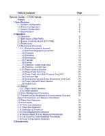
Table of Contents Service Guide - C7000 Series Preface 1 Specifications 1.1 System Configuration 1.2 Printer Configuration 1.3 Option Configuration 1.4 2.9 Cover-Open 2.10 Toner Low Detection 2.11 Page Size Detection 2.12 Operation at Power-on 2.13 Color Misalignment Detection 2.14 Version - Oki C7200 | Service Manual - Page 3
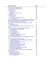
Printer Unit 45 ....Cassette Guide Assy (L), (R) 46 ....Duplex Unit 47 3.3 Replacing Parts 48 ....3.3.1 Top Cover 49 ....3.3.2 LED Assy / LED Assy Spring 50 ....3.3.3 Top Cover Unit 51 ....3.3.4 Control Panel Assy / Control Panel Bezel / LED Control 52 PWB / Toner 15 Drum Contact - Oki C7200 | Service Manual - Page 4
Cassette / Left Guide Assy ....3.3.40 Cassette / Right Guide Assy ....3.3.41 Fuser Unit ....3.3.42 Belt Unit ....3.3.43 Duplex Unit ....3.3.44 Guide Rails (L) CRM board replacement 4.3 Color Balance Adjustment 5 Period Maintenance 5.0 Periodic Maintenance 5.1 Parts Replaced Periodically 5.2 Cleaning - Oki C7200 | Service Manual - Page 5
........(3) Paper Size Error 138 ........(4) Image Drum Unit (ID) Up-and-Down Operation Error 139 ........(5) Fusing Unit Error 140 ........(6) Motor Fan Error 141 ....6.5.3 Troubleshooting image problems 142 ........(1) Light or Faded Image on Whole Page, or Color 143 Misalignment on - Oki C7200 | Service Manual - Page 6
Top Cover Assembly - Table 8-2 Printer Unit Chassis Figure 8-3 Printer Unit Chassis - Table 8-3 Paper Tray Guide - Figure 8-4 Paper Tray Guide - Table 8-4 Duplex Unit - Figure 8-5 Duplex Unit - Table 8-5 Centronics Parallel Interface B 2nd/3rd Tray Maintenance 1. Parts Replacement ....1.1 Cover Idle - Oki C7200 | Service Manual - Page 7
by users using the manual. l The parts used for the printers are electrostatic sensitive and, if handled improperly, may be damaged. It is strongly recommended that the products be maintained by Oki Data Authorized Repair Centers Oki Data. Copyright 1999, Okidata, Division of OKI America, Inc. All - Oki C7200 | Service Manual - Page 8
Service Guide - C7000 Series Chapter 1 Specifications 1.1 System Configuration Figure 1-1 shows the system configuration of the C7000 Series of printers. Page: 2 - Oki C7200 | Service Manual - Page 9
- Oki C7200 | Service Manual - Page 10
Copyright 1999, Okidata, Division of OKI America, Inc. All rights reserved. - Oki C7200 | Service Manual - Page 11
Service Guide - C7000 Series Chapter 1 Specifications 1.2 Printer Configuration The inside of the printer is composed of the following: l Electrophotographic Processor l Paper Paths l Controller Block (CU and PU) l Operator Panel l Power Units (High Voltage Unit and Low Voltage Unit) - Oki C7200 | Service Manual - Page 12
- Oki C7200 | Service Manual - Page 13
Copyright 1999, Okidata, Division of OKI America, Inc. All rights reserved. - Oki C7200 | Service Manual - Page 14
Service Guide - C7000 Series Chapter 1 Specifications 1.3 Option Configuration The following options are available for the C7000 Series of printers. (1) 2nd Tray / 3rd Tray Page: 4 (2) Duplex Unit (3) Expansion Memory 64/128/256 MB - Oki C7200 | Service Manual - Page 15
(4) Internal Hard Disk (5) OkiLAN 6200e NIC Copyright 1999, Okidata, Division of OKI America, Inc. All rights reserved. - Oki C7200 | Service Manual - Page 16
(7) Power Consumption (8) Frequency (9) Noise (10) Consumable Life Service Guide - C7000 Series Chapter 1 Specifications Page: 5 Height: 16.9 feeder support A6 and postal-card sizes.) Weight: 1st tray 55 kg to 90 kg (64 to 105g/m 2 ) Front feeder 55 kg to 140 kg (64 to 163g/ m 2 ) Color: 12 - Oki C7200 | Service Manual - Page 17
-29 to 50 with drum and toner Humidity condition Celsius Remarks 25 50% to 70% (for assurance of full-color printout quality) 26.8 Power off 35 40 (13) Printer Life 600,000 pages (on a A4-size basis) or five years Copyright 1999, Okidata, Division of OKI America, Inc. All rights - Oki C7200 | Service Manual - Page 18
Service Guide - C7000 Series Chapter 2 Operation Page: 6 2.0 Operation The C7000 Series of printers, tandem color electrophotographic page printers, adopt technologies such as an LED array, OPC, dry single-component non-magnetic developing, roller transfer and heat-compression fusing. A black- - Oki C7200 | Service Manual - Page 19
- Oki C7200 | Service Manual - Page 20
Copyright 1999, Okidata, Division of OKI America, Inc. All rights reserved. - Oki C7200 | Service Manual - Page 21
Service Guide - C7000 Series Chapter 2 Operation 2.1 Main board (CRM PWB) Figure 2-2 provides the block diagram of the main control board (CRM PWB). Page: 7 - Oki C7200 | Service Manual - Page 22
- Oki C7200 | Service Manual - Page 23
(1) CPU The CPU is PowerPC750, a 64-bit bus RISC processor, which inputs an 80-MHz CLK (=BUS CLK), and operates at 400MHz that is five times the input. (2) Secondary Cache SRAM SRAM is included as secondary cache of the CPU on the board. (3) ROM ROM is to be inserted into the three 168 pin - Oki C7200 | Service Manual - Page 24
Additional Board: (connected to PCI BUS) / Ethernet Board Copyright 1999, Okidata, Division of OKI America, Inc. All rights reserved. - Oki C7200 | Service Manual - Page 25
2.2 Engine Controller Board (K71 PWB) Service Guide - C7000 Series Chapter 2 Operation Page: 8 - Oki C7200 | Service Manual - Page 26
- Oki C7200 | Service Manual - Page 27
ROM (OKI MSM66Q577), controls the entire system. (2) General LSI This LSI (MG63P011-001LA), which is contained in the printer engine control socket. Correction values are stored in it. (5) Pulse Motor Driver The pulse motor driver (A2919SLBTR, A2918SWV) drives the eight pulse motors to revolve the - Oki C7200 | Service Manual - Page 28
-900V to 1.4KV -100 to 400V/ +300V Y, M, C, and K: -100V to -700V 0Kv to 7KV Use Voltage to charging roller Voltage to developing roller Voltage to toner supply roller Voltage to transfer roller Remarks Variable Copyright 1999, Okidata, Division of OKI America, Inc. All rights reserved. - Oki C7200 | Service Manual - Page 29
Service Guide - C7000 Series Chapter 2 Operation 2.4 Mechanical Processes Figure 2-4 shows the mechanical processes of the C7000 Series of printers. Page: 10 - Oki C7200 | Service Manual - Page 30
- Oki C7200 | Service Manual - Page 31
Copyright 1999, Okidata, Division of OKI America, Inc. All rights reserved. - Oki C7200 | Service Manual - Page 32
Service Guide - C7000 Series Chapter 2 Operation 2.4.1 Electrphotographic process (1) Electrophotographic processes (2) Charging (3) Exposure (4) Developing (5) Transfer (6) Fusing (7) Cleaning - waste toner area (8) Cleaning - transfer belt Copyright 1999, Okidata, Division of OKI - Oki C7200 | Service Manual - Page 33
the paper. (5) Cleaning - The cleaning blade removes residual toner from the OPC drum after the transfer. (6) Fusing - The toner image on the paper is fused into place through the application of heat and pressure to it. Copyright 1999, Okidata, Division of OKI America, Inc. All rights reserved. - Oki C7200 | Service Manual - Page 34
Service Guide - C7000 Series Chapter 2 Operation Page: 13 (2) Charging (2) Charging - Negative DC voltage is applied to the charging roller contacting the surface of the OPC drum. Copyright 1999, Okidata, Division of OKI America, Inc. All rights reserved. - Oki C7200 | Service Manual - Page 35
negative charge of the radiated portions of the drum surface attenuates in response to the intensity of the light and a latent electrostatic image responsive to the potentials of the surface is formed on the drum surface. Copyright 1999, Okidata, Division of OKI America, Inc. All rights reserved. - Oki C7200 | Service Manual - Page 36
the developing roller. (3) The toner is drawn by the latent electrostatic image at the contact portion between the OPC drum and the developing roller. The latent electrostatic image on the drum surface is made visible with the toner. Copyright 1999, Okidata, Division of OKI America, Inc. All rights - Oki C7200 | Service Manual - Page 37
the transfer roller to the paper surface at the contact portion between the transfer roller and the paper, the paper surface drawing the negatively charged toner from the drum surface. Copyright 1999, Okidata, Division of OKI America, Inc. All rights reserved. - Oki C7200 | Service Manual - Page 38
Service Guide - C7000 Series Chapter 2 Operation Page: 17 (6) Fusing (6) Fusing - When passing through between the heat roller and the backup roller, the toner image transferred to the paper is springs on both sides. Copyright 1999, Okidata, Division of OKI America, Inc. All rights reserved. - Oki C7200 | Service Manual - Page 39
Service Guide - C7000 Series Chapter 2 Operation Page: 18 (7) Cleaning - waste toner area (7) Cleaning - Non-fused, residual toner on the OPC drum is scraped with the cleaning blade and collected in the waste toner area of the toner cartridge. Copyright 1999, Okidata, Division of OKI America, Inc - Oki C7200 | Service Manual - Page 40
Service Guide - C7000 Series Chapter 2 Operation Page: 19 (8) Cleaning - transfer belt (8) Cleaning - Residual toner on the transfer belt is scraped with the cleaning blade and collected in the waste toner box of the transfer belt unit. Copyright 1999, Okidata, Division of OKI America, Inc. All - Oki C7200 | Service Manual - Page 41
Service Guide - C7000 Series Chapter 2 Operation 2.4.2 Paper running process Figure 2-5 shows the traveling of paper in the C7000 Series of printers. Page: 20 - Oki C7200 | Service Manual - Page 42
Copyright 1999, Okidata, Division of OKI America, Inc. All rights reserved. - Oki C7200 | Service Manual - Page 43
Service Guide - C7000 Series Chapter 2 Operation Page: 21 (1) Paper Feed from Tray 1. The running of the feed motor in the arrow direction (a) drives the feed roller and - Oki C7200 | Service Manual - Page 44
- Oki C7200 | Service Manual - Page 45
Copyright 1999, Okidata, Division of OKI America, Inc. All rights reserved. - Oki C7200 | Service Manual - Page 46
Service Guide - C7000 Series Chapter 2 Operation Page: 22 (2) Paper Feed from Multi-Purpose Tray (MT) 1. The release lever usually pushes down the hopping plate to a position that - Oki C7200 | Service Manual - Page 47
- Oki C7200 | Service Manual - Page 48
Copyright 1999, Okidata, Division of OKI America, Inc. All rights reserved. - Oki C7200 | Service Manual - Page 49
below each color's drum, and the transport belt between them. By the application of a fixed voltage, the transport belt and the transport roller feed paper on the transport belt into the fuser unit, transferring a toner image on each color's drum. Copyright 1999, Okidata, Division of OKI America - Oki C7200 | Service Manual - Page 50
Service Guide - C7000 Series Chapter 2 Operation Page: 24 (4) Driving and Up-and-Down unit to a specified level and stops to keep space to an extent between the drum and the transport belt (Figures 2-9-c and 2-9-e). The drum gear is not engaged with the driving gear and does not revolve. 3. When - Oki C7200 | Service Manual - Page 51
- Oki C7200 | Service Manual - Page 52
- Oki C7200 | Service Manual - Page 53
Copyright 1999, Okidata, Division of OKI America, Inc. All rights reserved. - Oki C7200 | Service Manual - Page 54
Service Guide - C7000 Series Chapter 2 Operation Page: 25 (5) Fuser Unit and Paper Ejection 1. A single-pulse motor drives the fuser unit and the eject rollers. In response to the running of the heat motor in the arrow direction (a), the heat roller turns. This roller fuses a toner image to paper - Oki C7200 | Service Manual - Page 55
- Oki C7200 | Service Manual - Page 56
Copyright 1999, Okidata, Division of OKI America, Inc. All rights reserved. - Oki C7200 | Service Manual - Page 57
Service Guide - C7000 Series Chapter 2 Operation Page: 26 (6) Duplex Unit 1. When the duplex unit receives an instruction from the printer to print on both sides of a sheet of paper, the solenoid opens the (2), (3) and (4), and ejected with the other side printed, and fed again into the printer. - Oki C7200 | Service Manual - Page 58
Copyright 1999, Okidata, Division of OKI America, Inc. All rights reserved. - Oki C7200 | Service Manual - Page 59
Service Guide - C7000 Series Chapter 2 Operation 2.5 Sensor 2.5.1 Paper related sensors 2.5.2 Other sensors Copyright 1999, Okidata, Division of OKI America, Inc. All rights reserved. Page: 27 - Oki C7200 | Service Manual - Page 60
2.5.1 Paper related sensors Service Guide - C7000 Series Chapter 2 Operation Page: 28 Sensor Entrance MT sensor Entrance Cassette sensor Entrance Belt sensor Exit sensor Function Detects the beginning of incoming paper - Oki C7200 | Service Manual - Page 61
: paper is present. OFF: Paper is absent. ON: paper is present. OFF: Paper is absent. ON: Stacker is full. OFF: Stacker is empty. Copyright 1999, Okidata, Division of OKI America, Inc. All rights reserved. - Oki C7200 | Service Manual - Page 62
Service Guide - C7000 Series Chapter 2 Operation Page: 29 2.5.2 Other sensors 1 Paper Empty each of colors, Y, M, C and K) This sensor checks whether the ID unit is in the up position or in the down position. 7 Toner K, Y, M and C sensors These sensors checks whether the waste toner cartridges are - Oki C7200 | Service Manual - Page 63
Upon correction of color misalignment, this sensor reads the alignment pattern printed at the right and left ends of the transfer belt (see section 2.13). Copyright 1999, Okidata, Division of OKI America, Inc. All rights reserved. - Oki C7200 | Service Manual - Page 64
Service Guide - C7000 Series Chapter 2 Operation Page: 30 2.6 Color Misalignment Correction Each of the C7000 Series of printers is equipped with 4 ID units and LED heads, which can cause color misalignment. This color misalignment is automatically corrected as follows: (1) Color alignment to be - Oki C7200 | Service Manual - Page 65
Service Guide - C7000 Series Chapter 2 Operation Page: 31 2.7 Transfer control Responds to Environmental Changes (Room Temperature and Relative Humidities) The C7000 Series of printers voltage. Environmental sensing table Copyright 1999, Okidata, Division of OKI America, Inc. All rights reserved. - Oki C7200 | Service Manual - Page 66
Service Guide - C7000 Series Chapter 2 Operation Page: 32 2.8 Paper Jam Detection The C7000 Series of printers detect paper jams after Jam Loading Jam MT Paper Empty Cassette 1, 2, or 3 Paper Empty Error Condition The entrance cassette sensor has not turned off within fixed time after its - Oki C7200 | Service Manual - Page 67
Copyright 1999, Okidata, Division of OKI America, Inc. All rights reserved. - Oki C7200 | Service Manual - Page 68
Service Guide - C7000 Series Chapter 2 Operation Page: 33 2.9 Cover-Open When the top cover of the printer is open, the cover-open microswitch turns off to cut the high voltage power and output of not less than 32V. At the same time, - Oki C7200 | Service Manual - Page 69
- Oki C7200 | Service Manual - Page 70
Copyright 1999, Okidata, Division of OKI America, Inc. All rights reserved. - Oki C7200 | Service Manual - Page 71
Service Guide - C7000 Series Chapter 2 Operation Page: 34 2.10 Toner Low Detection l Structure The toner low detection device consists of contact time between the sensor lever magnet and the stirring bar. Full Toner Condition l The stirring bar rotates in symchronization with the stirring gear. - Oki C7200 | Service Manual - Page 72
Low Condition The stirring bar reaches its highest position, then falls to its lowest position under its own weight because of the absence of toner resistance on the opposite side. In this situation, the bar-magnet contact time becomes long. By measuring the time, a toner low condition is detected. - Oki C7200 | Service Manual - Page 73
low is removed. l When the toner sensor remains unchanged for more than 15 cycles of 2.3 seconds, the toner sensor alarm is activated. l The toner sensor does not perform the detection while the drum motor is not running. Copyright 1999, Okidata, Division of OKI America, Inc. All rights reserved. - Oki C7200 | Service Manual - Page 74
Service Guide - C7000 Series Chapter 2 Operation Page: 35 2.11 Page Size Detection Via the cam moves jointly with the paper guide of the paper cassette, the four tab pieces are driven according to the set position of the paper guide 1999, Okidata, Division of OKI America, Inc. All rights reserved. - Oki C7200 | Service Manual - Page 75
Service Guide - C7000 RAM is judged as an error. (b) The order of mounted RAMs is checked. Out-of-standard order is judged as an error. (c) Each slot's RAM is after read-after-write checking. (6) Option unit check Before the printer goes into the operation mode, the presence of the option units - Oki C7200 | Service Manual - Page 76
Service Guide - C7000 Series Chapter 2 Operation Page: 37 2.13 Color Misalignment Detection Reflection-type optical sensors for detecting color misalignment (Z71-PCB) are mounted on the belt at the right and left ends, respectively, in front of the toner scraping (cleaning) blade which is at the - Oki C7200 | Service Manual - Page 77
- Oki C7200 | Service Manual - Page 78
Copyright 1999, Okidata, Division of OKI America, Inc. All rights reserved. - Oki C7200 | Service Manual - Page 79
Service Guide - C7000 Series Chapter 2 Operation Page: 38 2.14 Version Read of Units Replaced Periodically The version of each of the I/D, fuser unit and belt unit which are replaced purpose fuse in the unit is cut. Copyright 1999, Okidata, Division of OKI America, Inc. All rights reserved. - Oki C7200 | Service Manual - Page 80
Service Guide - C7000 Series Chapter 2 Operation Page: 39 2.15 Life Count for Units Replaced Periodically The life of each of the I/D, fuse unit and belt unit which are replaced periodically is counted as shown in the following table: Unit Name I/D (Image Drum be used). Fuser Unit The count - Oki C7200 | Service Manual - Page 81
Service Guide - C7000 Series Chapter 2 Operation Page: 40 2.16 Toner Consumption Detection The used toner amount is detected by counting the number of dots printed. The counting starts after toner low is removed. The sum of the counted values is stored in EEPROM. Upon detection of toner low, the - Oki C7200 | Service Manual - Page 82
the procedure for replacing the parts, assemblies and units in the field. The replacing procedure is given for detachment. To attach, use the reverse procedure. 3.1 Precautions in Replacing Parts 3.2 Parts layout 3.3 Replacing Parts Copyright 1999, Okidata, Division of OKI America, Inc. All rights - Oki C7200 | Service Manual - Page 83
Service Guide - C7000 Series Chapter 3 Disassembly 3.1 Precaution in Replacing Parts (1) Before starting parts replacement, remove the AC cable and interface cable. (a) Removing the AC cable i) Turn off ("o") the power switch of the printer. ii) Disconnect the AC inlet plug of the AC cable from - Oki C7200 | Service Manual - Page 84
(8) Do not place printed circuit boards directly on the equipment or floor. No. Service Tools 1 2 3 4 5 6 7 8 Tools No. 1-100 Philips screwdriver 1 Handy cleaner 1 LED Head cleaner P/N 51802901 1 Cleans LED head Copyright 1999, Okidata, Division of OKI America, Inc. All rights reserved. - Oki C7200 | Service Manual - Page 85
3.2 Parts Layout Service Guide - C7000 Series Chapter 3 Disassembly Page: 43 - Oki C7200 | Service Manual - Page 86
- Oki C7200 | Service Manual - Page 87
[Top Cover Assy} [Printer Unit] [Cassette Guide Assy (L), (R)] [Duplex Unit] Copyright 1999, Okidata, Division of OKI America, Inc. All rights reserved. - Oki C7200 | Service Manual - Page 88
Top Cover Assy Service Guide - C7000 Series Chapter 3 Disassembly Page: 44 - Oki C7200 | Service Manual - Page 89
- Oki C7200 | Service Manual - Page 90
Copyright 1999, Okidata, Division of OKI America, Inc. All rights reserved. - Oki C7200 | Service Manual - Page 91
Printer Unit [Printer Unit 1/2] Service Guide - C7000 Series Chapter 3 Disassembly Page: 45 - Oki C7200 | Service Manual - Page 92
- Oki C7200 | Service Manual - Page 93
Printer Unit 2/2] - Oki C7200 | Service Manual - Page 94
- Oki C7200 | Service Manual - Page 95
Copyright 1999, Okidata, Division of OKI America, Inc. All rights reserved. - Oki C7200 | Service Manual - Page 96
Cassette Guide Assy (L), (R) Service Guide - C7000 Series Chapter 3 Disassembly Page: 46 - Oki C7200 | Service Manual - Page 97
- Oki C7200 | Service Manual - Page 98
Copyright 1999, Okidata, Division of OKI America, Inc. All rights reserved. - Oki C7200 | Service Manual - Page 99
Duplex Unit Service Guide - C7000 Series Chapter 3 Disassembly Page: 47 - Oki C7200 | Service Manual - Page 100
- Oki C7200 | Service Manual - Page 101
- Oki C7200 | Service Manual - Page 102
Service Guide - C7000 Series Chapter 3 Disassembly Page: 48 3.3 Replacing Parts This section described how to replace the parts and assemblies shown in -purpose Tray Top Cover / Multi-purpose Tray Drive gear 3.3.15 Drum Contact Assys 3.3.16 Registration Roller Assy (A) / Registration Drive Gear - Oki C7200 | Service Manual - Page 103
3.3.21 Duplex Guide Assy 3.3.22 Electrical Chassis Cooling Fan 3.3.23 Printer Engine Controller PWB 3.3.24 Printer Unit Chassis 3.3.25 Entrance Cassette Sensor Actuator 3.3.26 Entrance Sensor PWB 3.3.27 Entrance MT Sensor Actuator and Entrance Belt Sensor Actuator 3.3.28 Fuser Exit Roller 3.3.29 - Oki C7200 | Service Manual - Page 104
3.3.43 Duplex Unit 3.3.44 Guide Rails (L) and (R) 3.3.45 Duplex Transport Assembly 3.3.46 CU Assy Copyright 1999, Okidata, Division of OKI America, Inc. All rights reserved. - Oki C7200 | Service Manual - Page 105
Service Guide - C7000 Series Chapter 3 Disassembly 3.3.1 Top Cover (1) Open the Top Cover assy. (2) Remove the nine screws (1) to detach the top cover (2). Page: 49 Copyright 1999, Okidata, Division of OKI America, Inc. All rights reserved. - Oki C7200 | Service Manual - Page 106
Service Guide - C7000 Series Chapter 3 Disassembly Page: 50 3.3.2 LED Assy / LED Assy Spring (1) Open the top cover (1). (2) Remove the three cables, and unhook the LED Assy (2) at - Oki C7200 | Service Manual - Page 107
Copyright 1999, Okidata, Division of OKI America, Inc. All rights reserved. - Oki C7200 | Service Manual - Page 108
Service Guide - C7000 Series Chapter 3 Disassembly Page: 51 3.3.3 Top Cover Unit (1) Remove the top cover (see section 3.3.1). (2) Remove the rear cover (see section 3.3.10). (3) Remove the left - Oki C7200 | Service Manual - Page 109
Copyright 1999, Okidata, Division of OKI America, Inc. All rights reserved. - Oki C7200 | Service Manual - Page 110
- Oki C7200 | Service Manual - Page 111
Service Guide - C7000 Series Chapter 3 Disassembly Page: 52 3.3.4 Control Panel Assy / Control Panel Bezel / LED Control PWB / Toner Sensors / Stacker Full Sensor / Control Panel / Control Panel Tape Harness / Eject Rollers (1) Detach the control panel bezel placed in the control panel Assy (2). - Oki C7200 | Service Manual - Page 112
Copyright 1999, Okidata, Division of OKI America, Inc. All rights reserved. - Oki C7200 | Service Manual - Page 113
Service Guide - C7000 Series Chapter 3 Disassembly Page: 53 3.3.5 Top Cover Handle / Top Cover Latch / Top Cover Latch Spring (1) Remove the two screws (1) to detach the top cover - Oki C7200 | Service Manual - Page 114
- Oki C7200 | Service Manual - Page 115
Copyright 1999, Okidata, Division of OKI America, Inc. All rights reserved. - Oki C7200 | Service Manual - Page 116
Service Guide - C7000 Series Chapter 3 Disassembly 3.3.6 Eject Guide Assy (1) Remove the five screws (1) to detach the eject guide assy (2). Page: 54 - Oki C7200 | Service Manual - Page 117
- Oki C7200 | Service Manual - Page 118
Copyright 1999, Okidata, Division of OKI America, Inc. All rights reserved. - Oki C7200 | Service Manual - Page 119
Service Guide - C7000 Series Chapter 3 Disassembly 3.3.7 Cassette Assy / Front Cover Assy / Front Cover Inner Baffle (1) Detach the cassette assy (1). (2) Open the front cover (2), and disengage it at two places to detach it. (3) Detach the front cover inner baffle (3). Page: 55 - Oki C7200 | Service Manual - Page 120
Copyright 1999, Okidata, Division of OKI America, Inc. All rights reserved. - Oki C7200 | Service Manual - Page 121
Service Guide - C7000 Series Chapter 3 Disassembly 3.3.8 Retard Pad Assy / Retard Pad Assy Spring (1) Remove the cassette (1). (2) Detach the retard pad assy (2) (at the same time, the spring (3) becomes detached). Page: 56 - Oki C7200 | Service Manual - Page 122
- Oki C7200 | Service Manual - Page 123
Copyright 1999, Okidata, Division of OKI America, Inc. All rights reserved. - Oki C7200 | Service Manual - Page 124
3.3.9 Feed Roller and Nudger Roller (1) Remove the cassette (1). (2) Unlatch and demount the feed roller (1). (3) Unlatch and demount the nudger roller (2). Service Guide - C7000 Series Chapter 3 Disassembly Page: 57 - Oki C7200 | Service Manual - Page 125
Copyright 1999, Okidata, Division of OKI America, Inc. All rights reserved. - Oki C7200 | Service Manual - Page 126
the four screws (2) to detach the rear cover (1). Note: When attaching the rear cover, take care not to allow the spring (3) to get caught in parts. Page: 58 Copyright 1999, Okidata, Division of OKI America, Inc. All rights reserved. - Oki C7200 | Service Manual - Page 127
- Oki C7200 | Service Manual - Page 128
Service Guide - C7000 Series Chapter 3 Disassembly 3.3.11 Face-Up Tray (1) Open the face-up tray (1) in the arrow direction, and disengage it at two places to detach it. Page: 59 - Oki C7200 | Service Manual - Page 129
Copyright 1999, Okidata, Division of OKI America, Inc. All rights reserved. - Oki C7200 | Service Manual - Page 130
Service Guide - C7000 Series Chapter 3 Disassembly 3.3.12 Left Side Cover (1) Open the top cover (1). (2) Open the front cover (2) and undo the screw (3). (3) Remove the four screws (4) to detach the left side cover (5). Page: 60 - Oki C7200 | Service Manual - Page 131
Copyright 1999, Okidata, Division of OKI America, Inc. All rights reserved. - Oki C7200 | Service Manual - Page 132
Service Guide - C7000 Series Chapter 3 Disassembly 3.3.13 Right Side Cover (1) Open the top cover (1). (2) Open the front cover (2) and undo the screw (3). (3) Remove the four screws (4) to detach the right side cover (5). Page: 61 - Oki C7200 | Service Manual - Page 133
- Oki C7200 | Service Manual - Page 134
Copyright 1999, Okidata, Division of OKI America, Inc. All rights reserved. - Oki C7200 | Service Manual - Page 135
Service Guide - C7000 Series Chapter 3 Disassembly Page: 62 3.3.14 Multi-purpose Tray Assy / Links Multipurpose Tray Assy / Multipurpose Tray Cover Assy / Links / Multipurpose Tray Top Cover / Multipurpose - Oki C7200 | Service Manual - Page 136
Copyright 1999, Okidata, Division of OKI America, Inc. All rights reserved. - Oki C7200 | Service Manual - Page 137
Service Guide - C7000 Series Chapter 3 Disassembly Page: 63 3.3.15 Drum Contact Assys (1) Insert a flatblade screwdriver between the printer case and the drum contact assy (1) to demount the drum contact assy (1). - Oki C7200 | Service Manual - Page 138
Copyright 1999, Okidata, Division of OKI America, Inc. All rights reserved. - Oki C7200 | Service Manual - Page 139
Service Guide - C7000 Series Chapter 3 Disassembly 3.3.16 Registration Roller Assy (A) / Registration Drive Gear (A) (1) Remove the left side cover (see section 3.3.12). (2) Remove the right side cover (see - Oki C7200 | Service Manual - Page 140
Copyright 1999, Okidata, Division of OKI America, Inc. All rights reserved. - Oki C7200 | Service Manual - Page 141
Service Guide - C7000 Series Chapter 3 Disassembly 3.3.17 Registration Roller Assy (B) (1) Remove the cassette Assy. (2) Open the front cover. (3) Remove the right side cover (see section 3.3.13). (4) Remove - Oki C7200 | Service Manual - Page 142
- Oki C7200 | Service Manual - Page 143
Copyright 1999, Okidata, Division of OKI America, Inc. All rights reserved. - Oki C7200 | Service Manual - Page 144
Service Guide - C7000 Series Chapter 3 Disassembly Page: 66 3.3.18 Registration Clutch and Registration Motor Assy (1) Remove the left side cover (see section 3.3.12). (2) Remove the left plate - Oki C7200 | Service Manual - Page 145
Copyright 1999, Okidata, Division of OKI America, Inc. All rights reserved. - Oki C7200 | Service Manual - Page 146
Service Guide - C7000 Series Chapter 3 Disassembly 3.3.19 Main Cooling Fan (1) Unhook the connector (1), and remove the screw (2) and the cooling fan (3). Note: When attaching the cooling fan, observe its correct orientation. Page: 67 - Oki C7200 | Service Manual - Page 147
Copyright 1999, Okidata, Division of OKI America, Inc. All rights reserved. - Oki C7200 | Service Manual - Page 148
Service Guide - C7000 Series Chapter 3 Disassembly Page: 68 3.3.20 Color Registration Sensor Assy (1) Remove the two screws (1) and the two connectors to demount the color registration sensor assy (2). (2) Remove the earth plate B (3). - Oki C7200 | Service Manual - Page 149
Copyright 1999, Okidata, Division of OKI America, Inc. All rights reserved. - Oki C7200 | Service Manual - Page 150
- Oki C7200 | Service Manual - Page 151
3.3.21 Duplex Guide Assy (1) Unlatch and demount the duplex guide (1). Service Guide - C7000 Series Chapter 3 Disassembly Page: 69 - Oki C7200 | Service Manual - Page 152
- Oki C7200 | Service Manual - Page 153
Copyright 1999, Okidata, Division of OKI America, Inc. All rights reserved. - Oki C7200 | Service Manual - Page 154
Service Guide - C7000 Series Chapter 3 Disassembly 3.3.22 Electrical Chassis Cooling Fan (1) Unscrew the screws (1) to remove the plate A (2). (2) Unscrew the screws (3) to remove the shield plate B (4). (3) Remove the printer engine controller PWB (see section 3.3.30). (4) Unscrew the screws (5) to - Oki C7200 | Service Manual - Page 155
Copyright 1999, Okidata, Division of OKI America, Inc. All rights reserved. - Oki C7200 | Service Manual - Page 156
right side cover (see section 3.3.13). (2) Remove the left plate Assy (see section 3.3.22). (3) Remove the five screws (1) and all the connectors to demount the printer engine controller PWB (2). Copyright 1999, Okidata, Division of OKI America, Inc. All rights reserved. - Oki C7200 | Service Manual - Page 157
Service Guide - C7000 Series Chapter 3 Disassembly 3.3.24 Printer Unit Chassis (1) Unscrew the two screws (1) and remove the AC inlet (2). (2) Unscrew the four black screws (3) and five screws (4) to detach the printer unit chassis (5). (3) Unscrew the four black screws (6) and remove the left top - Oki C7200 | Service Manual - Page 158
- Oki C7200 | Service Manual - Page 159
Copyright 1999, Okidata, Division of OKI America, Inc. All rights reserved. - Oki C7200 | Service Manual - Page 160
Service Guide - C7000 Series Chapter 3 Disassembly 3.3.25 Entrance Cassette Sensor Actuator (1) Remove the printer unit chassis (see section 3.3.24). (2) Turn over the main chassis. (3) Remove the two clamps with needlenose pliers to detach the entrance cassette sensor actuator (1). Page: 73 - Oki C7200 | Service Manual - Page 161
Copyright 1999, Okidata, Division of OKI America, Inc. All rights reserved. - Oki C7200 | Service Manual - Page 162
Service Guide - C7000 Series Chapter 3 Disassembly 3.3.26 Entrance Sensor PWB (1) Remove the registration roller assb (B) (see section 3.3.17). (2) Remove the two screws (10 to detach the entrance sensor PWB (2). Page: 74 Copyright 1999, Okidata, Division of OKI America, Inc. All rights reserved. - Oki C7200 | Service Manual - Page 163
- Oki C7200 | Service Manual - Page 164
Service Guide - C7000 Series Chapter 3 Disassembly 3.3.27 Entrance MT Sensor Actuator and Entrance Belt Sensor Actuator (1) Remove the entrance sensor PWB (R71) (see section 3.3.26). (2) Unlatch and - Oki C7200 | Service Manual - Page 165
Copyright 1999, Okidata, Division of OKI America, Inc. All rights reserved. - Oki C7200 | Service Manual - Page 166
Service Guide - C7000 Series Chapter 3 Disassembly 3.3.28 Fuser Exit Roller (1) Unscrew the two screws (1) to remove the duplex gate solenoid Assy (2). (2) Unscrew the screw (3) to remove the fuser exit roller contact (4). (3) Remove the fuser drive gear -A (5) and fuser drive gear -A (6). (4) - Oki C7200 | Service Manual - Page 167
Copyright 1999, Okidata, Division of OKI America, Inc. All rights reserved. - Oki C7200 | Service Manual - Page 168
- Oki C7200 | Service Manual - Page 169
Service Guide - C7000 Series Chapter 3 Disassembly 3.3.29 Exit Sensor Assy (1) Remove the fuser exit roller (see section 3.3.28). (2) Remove the screw (1) and connector to detach the (red and blue) exit sensor assy (2). Page: 77 - Oki C7200 | Service Manual - Page 170
Copyright 1999, Okidata, Division of OKI America, Inc. All rights reserved. - Oki C7200 | Service Manual - Page 171
- Oki C7200 | Service Manual - Page 172
Service Guide - C7000 Series Chapter 3 Disassembly 3.3.30 Fuser Latching Handle (L) (1) Remove the latching handle spring (1). (2) Unscrew the screw (2) to detach the fuser latching handle (L) (3). Page: 78 - Oki C7200 | Service Manual - Page 173
- Oki C7200 | Service Manual - Page 174
Copyright 1999, Okidata, Division of OKI America, Inc. All rights reserved. - Oki C7200 | Service Manual - Page 175
Service Guide - C7000 Series Chapter 3 Disassembly 3.3.31 Belt Motor Assy (1) Remove the fuser latching handle (R) (see section 3.3.32). (2) Remove the two screws (1) to detach the two connectors (2). (3) Detach the belt motor Assy (3). Page: 79 - Oki C7200 | Service Manual - Page 176
Copyright 1999, Okidata, Division of OKI America, Inc. All rights reserved. - Oki C7200 | Service Manual - Page 177
- Oki C7200 | Service Manual - Page 178
Service Guide - C7000 Series Chapter 3 Disassembly 3.3.32 Fuser Latching Handle (R) (1) Remove the printer unit chassis (see section 3.3.24). (2) Remove the E ring (1). (3) Remove the fuser latching handle spring (2) to detach the fuser latching handle (R) (3). Page: 80 - Oki C7200 | Service Manual - Page 179
Copyright 1999, Okidata, Division of OKI America, Inc. All rights reserved. - Oki C7200 | Service Manual - Page 180
Service Guide - C7000 Series Chapter 3 Disassembly 3.3.33 Main Motor Assy (1) Remove the belt motor assy (see section 3.3.31). (2) Remove all the connectors. (3) Remove the four screws (1) to detach the main motor assy (2). Page: 81 - Oki C7200 | Service Manual - Page 181
Copyright 1999, Okidata, Division of OKI America, Inc. All rights reserved. - Oki C7200 | Service Manual - Page 182
Service Guide - C7000 Series Chapter 3 Disassembly 3.3.34 Main Feeder Drive Motor (1) Remove the two screws (1) to detach the main feeder drive motor (2). (2) Unscrew the screw (3) to remove - Oki C7200 | Service Manual - Page 183
- Oki C7200 | Service Manual - Page 184
Copyright 1999, Okidata, Division of OKI America, Inc. All rights reserved. - Oki C7200 | Service Manual - Page 185
Service Guide - C7000 Series Chapter 3 Disassembly 3.3.35 Contact Assy / Left Plate Assy (1) Remove the printer unit chassis (see section 3.3.24). (2) Remove the four screws (1) to detach the left plate Assy (2). (3) Remove the screw (3) to detach the contact Assy (4). Page: 83 - Oki C7200 | Service Manual - Page 186
Copyright 1999, Okidata, Division of OKI America, Inc. All rights reserved. - Oki C7200 | Service Manual - Page 187
Service Guide - C7000 Series Chapter 3 Disassembly 3.3.36 Low Voltage Power Supply (1) Remove the printer unit chassis (see section 3.3.24). (2) Unhook the connector (1). (3) Unscrew the screw (2) to remove the earth cable (3). (4) Unscrew the six screws (4) to detach the low voltage - Oki C7200 | Service Manual - Page 188
Copyright 1999, Okidata, Division of OKI America, Inc. All rights reserved. - Oki C7200 | Service Manual - Page 189
Service Guide - C7000 Series Chapter 3 Disassembly 3.3.37 High Voltage Power Supply (1) Remove the contact Assy (see section 3.3.35). (2) Unhook the connector of the high voltage power supply (2). (3) - Oki C7200 | Service Manual - Page 190
- Oki C7200 | Service Manual - Page 191
Copyright 1999, Okidata, Division of OKI America, Inc. All rights reserved. - Oki C7200 | Service Manual - Page 192
Service Guide - C7000 Series Chapter 3 Disassembly Page: 86 3.3.38 Main Feed Assy (1) Remove the printer unit chassis (see section 3.3.24). (2) Remove the low voltage power supply and high voltage power supply (see sections 3.3.36 and 3.3.37). (3) Unscrew the five screws (1) - Oki C7200 | Service Manual - Page 193
- Oki C7200 | Service Manual - Page 194
Copyright 1999, Okidata, Division of OKI America, Inc. All rights reserved. - Oki C7200 | Service Manual - Page 195
Service Guide - C7000 Series Chapter 3 Disassembly Page: 87 3.3.39 Cassette / Left Guide Assy (1) Remove the printer unit chassis (see section 3.3.24). (2) Remove the main feed Assy (see section 3.3.38). (3) Remove the three screws (1) to detach the left cassette guide Assy (2). At the same time, - Oki C7200 | Service Manual - Page 196
- Oki C7200 | Service Manual - Page 197
Copyright 1999, Okidata, Division of OKI America, Inc. All rights reserved. - Oki C7200 | Service Manual - Page 198
Service Guide - C7000 Series Chapter 3 Disassembly Page: 88 3.3.40 Cassette / Right Guide Assy (1) Remove the printer unit chassis (see section 3.3.24). (2) Remove the main feed Assy (see section 3.3.38). (3) Remove the five screws (1) to detach the right cassette guide Assy (2). At the same time, - Oki C7200 | Service Manual - Page 199
Copyright 1999, Okidata, Division of OKI America, Inc. All rights reserved. - Oki C7200 | Service Manual - Page 200
- Oki C7200 | Service Manual - Page 201
Service Guide - C7000 Series Chapter 3 Disassembly 3.3.41 Fuser Unit (1) Open the top cover (1). (2) Push the right and left fuser levers (blue) (2) in the arrow direction to detach the fuser unit (3). Page: 89 Copyright 1999, Okidata, Division of OKI America, Inc. All rights reserved. - Oki C7200 | Service Manual - Page 202
Service Guide - C7000 Series Chapter 3 Disassembly 3.3.42 Belt Unit (1) Open the top cover (1). (2) Remove the I/D unit. (3) Push the lever (blue) (2) in the arrow direction, raise the handle (blue) and detach the belt unit (3). Page: 90 - Oki C7200 | Service Manual - Page 203
Copyright 1999, Okidata, Division of OKI America, Inc. All rights reserved. - Oki C7200 | Service Manual - Page 204
Service Guide - C7000 Series Chapter 3 Disassembly 3.3.43 Duplex Unit (1) Remove the cassette Assy, the front cover Assy and the front cover inner baffle. (2) Unlatch the rear at the right and left, and pull the duplex unit 1 toward the front. Page: 91 Copyright 1999, Okidata, Division of OKI - Oki C7200 | Service Manual - Page 205
Service Guide - C7000 Series Chapter 3 Disassembly 3.3.44 Guide Rails (L) and (R) (1) Remove the duplex unit (see section 3.3.43). (2) Remove the six screws 1 to detach the guide rails (L) 2 and (R) 3. Page: 92 Copyright 1999, Okidata, Division of OKI America, Inc. All rights reserved. - Oki C7200 | Service Manual - Page 206
- Oki C7200 | Service Manual - Page 207
Service Guide - C7000 Series Chapter 3 Disassembly Page: 93 3.3.45 Duplex Transport Assembly (1) Turn over the duplex transport Assy. (2) Unscrew the three screws (1) and five screws (2) to detach - Oki C7200 | Service Manual - Page 208
- Oki C7200 | Service Manual - Page 209
Copyright 1999, Okidata, Division of OKI America, Inc. All rights reserved. - Oki C7200 | Service Manual - Page 210
screws 1. 2. Pull the controller board 2 out. 3. Place the controller board 2 on a flat table. (2) Detaching Fan 1. Remove the connector 3. 2. Remove the two screws 4. 3. Detach the fan 5. Service Guide - C7000 Series Chapter 3 Disassembly Page: 94 - Oki C7200 | Service Manual - Page 211
(3) Removing the CRM Board - Oki C7200 | Service Manual - Page 212
1. Unscrew the four screws (6) to remove the fan bracket (7). 2. Unscrew the four screws (8) to remove the plate support (9) and the guide rail A (10). 3. Unscrew the two screws (11) to remove the guide rail (11) . 4. Unscrew the two screws (12) and three screws (14), then detach the CRM board (15). - Oki C7200 | Service Manual - Page 213
- Oki C7200 | Service Manual - Page 214
Copyright 1999, Okidata, Division of OKI America, Inc. All rights reserved. - Oki C7200 | Service Manual - Page 215
on the C7000 Series of printers are made by key entry on the operator panel. In addition to a standard menu, there is a maintenance menu in each printer. Select the one that serves the purpose of intended adjustment. Copyright 1999, Okidata, Division of OKI America, Inc. All rights reserved - Oki C7200 | Service Manual - Page 216
Service Guide - C7000 Series Chapter 4 Adjustments 4.1 Maintenance Modes and Their Functions 4.1.1 Maintenance Menu 4.1.2 Engine Maintenance Menu 4.1.3 CRM Board Adjustments Copyright 1999, Okidata, Division of OKI America, Inc. All rights reserved. Page: 96 - Oki C7200 | Service Manual - Page 217
Service Guide - C7000 Series Chapter 4 Adjustments Page: 97 4.1.1 Maintenance Menu The With dispersed or snowed printing in the part at high-density, decrease the value. With unclear printing, increase the value. Implements fine adjustment of COLOR printing on normal paper when unclear characters - Oki C7200 | Service Manual - Page 218
Copyright 1999, Okidata, Division of OKI America, Inc. All rights reserved. - Oki C7200 | Service Manual - Page 219
Service Guide - C7000 Series Chapter 4 Adjustments 2, which sets the consumable counter and tests the color registration adjustment function, does not require relatively special knowledge - continuous 4.1.2.9 Error Messages and their Details Copyright 1999, Okidata, Division of OKI America, Inc. - Oki C7200 | Service Manual - Page 220
Service Guide - C7000 Series Chapter 4 Adjustments 4.1.2.1 Operator panel Operational descriptions about the self-diagnosis are premised on the following operator panel layout. Page: 99 Copyright 1999, Okidata, Division of OKI America, Inc. All rights reserved. - Oki C7200 | Service Manual - Page 221
Service Guide - C7000 Series Chapter 4 Adjustments 4.1.2.2 General self-diagnosis mode (level 1) Following is the - Continuous 4.1.2.2.1 Entering self-diagnosis mode (level 1) 4.1.2.2.2 Exiting self-diagnosis mode Copyright 1999, Okidata, Division of OKI America, Inc. All rights reserved. Page: 100 - Oki C7200 | Service Manual - Page 222
Service Guide - C7000 Series Chapter 4 Adjustments Page: 101 4.1.2.2.1 Entering self-diagnosis mode (level 1) 1. Detach the main controller board. 2. 5 55 55 keys (pressing 1 11 11 and 5 55 55 keys rotates the menu items). Copyright 1999, Okidata, Division of OKI America, Inc. All rights reserved. - Oki C7200 | Service Manual - Page 223
Service Guide - C7000 Series Chapter 4 Adjustments Page: 102 4.1.2.2.2 Exiting self-diagnosis mode 1. While "ENGINE DIAG MODE XX.XX" is displayed, press the (0) key, or turn the power off and, after ten seconds, on again. Copyright 1999, Okidata, Division of OKI America, Inc. All rights reserved. - Oki C7200 | Service Manual - Page 224
Service Guide - C7000 Series Chapter 4 Adjustments Page: 103 4.1.2.3 Switch scan test This self-diagnosis is used when the input sensor and the switch are checked. 1. Enter the - Oki C7200 | Service Manual - Page 225
- Oki C7200 | Service Manual - Page 226
- Oki C7200 | Service Manual - Page 227
Copyright 1999, Okidata, Division of OKI America, Inc. All rights reserved. - Oki C7200 | Service Manual - Page 228
Service Guide - C7000 Series Chapter 4 Adjustments Page: 104 4.1.2.4 Motor and clutch test This self-check routine is used for testing the motor and clutch. 1. Go to the - Oki C7200 | Service Manual - Page 229
Unit Name Display BLACK-ID MOTOR YELLOW-ID MOTOR MAGENTA-ID MOTOR CYAN-ID MOTOR BELT MTOR FUSER MOTOR Driving Constraints Remove all the IDs (B, Y, M and C) to drive the unit. Remove all the IDs (B, Y, M and C) to drive the unit. Remove all the IDs (B, Y, M - Oki C7200 | Service Manual - Page 230
BLOCK FAN) Remove the cassette 1 to drive the unit. Remove the cassette 2 to drive the unit. - Remove the cassette 3 to drive the unit. - - - Copyright 1999, Okidata, Division of OKI America, Inc. All rights reserved. EXIT TRAY1 CASSETTE EXIT TRAY2 CASSETTE - EXIT TRAY3 CASSETTE - - - - Oki C7200 | Service Manual - Page 231
Service Guide setting item and its setting are displayed on the upper and lower parts, respectively. Pressing the (3) key increments a setting. Pressing the (7) step 3 as necessary. Display PRINT EXECUTE TEST PATTERN (TBD) CASSET COLOR FUSER DUPLEX Setting 1 2 3 TRAY1 TRAY2 TRAY3 FF NONE ON OFF ON - Oki C7200 | Service Manual - Page 232
). l The display is changed at the press of the 3 33 33 key. YR, MR, CR and KR are the transfer voltage measurements for transfer roller colors (in KV). 4. While "PRINT EXECUTE" is indicated in the lower display after the Item 2 procedure, press Key (3) to start test printing with the values set - Oki C7200 | Service Manual - Page 233
the Detail column in the table specified below is found, the corresponding alarm message appears on the operator panel and test printing is suspended. (For error details, see Sec. 4.1.2.9 Error Messages and their Details.) Print Patterns: Patterns 0, 8 ~15: Blank paper output - Oki C7200 | Service Manual - Page 234
- Oki C7200 | Service Manual - Page 235
- Oki C7200 | Service Manual - Page 236
5. Steps 2 through 4 to be repeated on an as needed basis. 6. Touch the (4) key to end the test (the display is restored to step 1). Copyright 1999, Okidata, Division of OKI America, Inc. All rights reserved. - Oki C7200 | Service Manual - Page 237
Service Guide - drum. Initial Value Unit 0 - Initializes the internal counter after the 0 - replacement of the belt unit. Initializes the internal counter after the 0 - replacement of the fuser unit. Initializes the internal counter after the 0 - recovery from each toner low error - Oki C7200 | Service Manual - Page 238
the Y-axis right-correction 0 value for the LED head (Yellow/Magenta/Cyan). Initializes all the items that have been set using levels 2 and 3. Copyright 1999, Okidata, Division of OKI America, Inc. All rights reserved. inch 1/1200 inch 1/1200 inch - Oki C7200 | Service Manual - Page 239
Service Guide is restored). Item Fuser Unit Upper Display FUSER UNIT Lower Display color's ID unit after the installation of that unit to date into a count in letter (A4) size paper sheets and shows it. Shows the remaining amount of each color's toner. Copyright 1999, Okidata, Division of OKI - Oki C7200 | Service Manual - Page 240
- Oki C7200 | Service Manual - Page 241
Service Guide - C7000 -diagnosis mode, and the (1) and (5) keys down until the upper display "PRINTER STATUS" appears (the (1) key is for item increment and the (5) key each color's ID into a count in letter paper sheets to set it. Copyright 1999, Okidata, Division of OKI America, Inc. All - Oki C7200 | Service Manual - Page 242
LEFT CYAN SENSOR ERROR RIGHT CYAN SENSOR ERROR LEFT CYAN TONER LOW CYAN TONER EMPTY CYAN DRUM LIFE OVER CU FAN MOTOR ERROR CALIBRATION ERROR CUSTOM DIAGNOSTICS MODE DUPLEX I/F ERROR DISPOSAL TONER SENSOR ERROR DISPOSAL TONER NEARFULL DISPOSAL TONER FULL DIAGNOSTICS MODE Service Guide - C7000 Series - Oki C7200 | Service Manual - Page 243
jam Tray1 hopping error Tray2 hopping error Tray3 hopping error Front feeder hopping error Duplex unit hopping error Tray4 hopping error Tray5 hopping error Initializing after turning on the printer Initializing after a cover is opened / closed Initializing after automatic color-registrat Feed jam - Oki C7200 | Service Manual - Page 244
OPEN MISSING ERROR FINISHER I/F ERRORS MISSING BELT UNIT MISSING FUSER UNIT MISSING BLACK DRUM MISSING CYAN DRUM MISSING MAGENTA DRUM MISSING YELLOW DRUM MAGENTA DRUM UP/DOWN ERROR MAGENTA DRUM UNIT FUSER CUT ERROR MAGENTA TONER SENSOR ERROR MAGENTA LED HEAD ERROR MAGENTA IRREGULAR ERROR MAGENTA - Oki C7200 | Service Manual - Page 245
LOW TEMPER UPPER HEATER HIGH TEMPER UPPER HEATER OPEN ERROR UPPER HEATER SHORT ERROR WARMING UP WDT ERROR YELLOW DRUM UP/DOWN ERROR YELLOW DRUM UNIT FUSE CUT ERROR YELLOW TONER SENSOR ERROR YELLOW LED HEAD ERROR YELLOW IRREGULAR ERROR YELLOW REGISTRATION OUT LEFT YELLOW REGISTRATION OUT RIGHT YELLOW - Oki C7200 | Service Manual - Page 246
Tray3 hopping error Front feeder hopping error Duplex unit hopping error Tray4 hopping error Tray5 hopping error INPATH --- Information of paper that stays on the paper path INFEED --- Information of paper that stays at the paper entrance Copyright 1999, Okidata, Division of OKI America, Inc. All - Oki C7200 | Service Manual - Page 247
the EEPROM, enter the maintenance mode and select the EEPROM RESET item after the general start-up. 4.1.3.1 Short plug settings 4.1.3.2 Printings singly using controller-equipped printer Copyright 1999, Okidata, Division of OKI America, Inc. All rights reserved. - Oki C7200 | Service Manual - Page 248
Service Guide - C7000 Series Chapter 4 Adjustments Page: 111 4.1.3.1 Short plug settings The CRM board has 2-Bank DIMM) A 1-bank DIMM (dual-sided 1 bank) is only a prototype and, in production-run printers, does not exist. Copyright 1999, Okidata, Division of OKI America, Inc. All rights reserved. - Oki C7200 | Service Manual - Page 249
Service Guide - C7000 Series Chapter 4 Adjustments Page: 112 4.1.3.2 Printing Menu Reports Menu Map Printing The program versions, the controller block configuration and other configurations and settings of the printer are printed. Operation: (Press of Switches) Without HDD: "0" --> "3" --> "3" - Oki C7200 | Service Manual - Page 250
Copyright 1999, Okidata, Division of OKI America, Inc. All rights reserved. - Oki C7200 | Service Manual - Page 251
below. Adjustment and correction of color registration are always required for each part replacement. Replaced Part LED Head Drum Cartridge (Y, M, C, K) Fuser Unit Belt Cassette Assy PU (K71 Bord) CU (CRM Board) Adjustment Color balance adjustment. Color balance adjustment. Not required. Not - Oki C7200 | Service Manual - Page 252
of engine EEPROM). When the "SERVICE CALL XX" (an engine EEPROM error) message is displayed on the operator panel, the EEPROM must be replaced with new one. In this case, perform the operation described in Section 4.2.2. Copyright 1999, Okidata, Division of OKI America, Inc. All rights reserved - Oki C7200 | Service Manual - Page 253
an error occurs in the each unit's life count until the unit is replaced. Following is counts cleared after the replacement of the EEPROM. Item Fuser Transfer Belt Black Imaging Drum Cyan Imaging Drum Magenta Imaging Drum Yellow Imaging Drum Black Toner Cyan Toner Magenta Toner Yellow Toner Total - Oki C7200 | Service Manual - Page 254
Black Impressions Cyan Impressions Magenta Impressions Yellow Impressions Total number of Pages Printed The number of pages printed after the installation of a new ID unit. Copyright 1999, Okidata, Division of OKI America, Inc. All rights reserved. - Oki C7200 | Service Manual - Page 255
Service Guide - C7000 Series Chapter 4 Adjustments Page: 116 4.2.3 EEPROM replacement to inherit user-defined settings and font installation information). When the user's EEPROM is unusable due to its problem, use the new one on the new board, where the destination of the new board must be set - Oki C7200 | Service Manual - Page 256
Service Guide - C7000 Series Chapter 4 Adjustments Page: 117 4.3 Color Balance Adjustment Color balance has been adjusted appropriately when a printer is shipped from the plant. However, it may be out of the appropriate balance during use. In such a case, color the color at the [(] part on the - Oki C7200 | Service Manual - Page 257
Copyright 1999, Okidata, Division of OKI America, Inc. All rights reserved. - Oki C7200 | Service Manual - Page 258
Service Guide - C7000 Series Chapter 5 Period Maintenance 5.0 Periodic Maintenance 5.1 Parts Replaced Periodically 5.2 Cleaning 5.3 Cleaning LED Lens Array 5.4 Cleaning Pickup Roller Copyright 1999, Okidata, Division of OKI America, Inc. All rights reserved. Page: 118 - Oki C7200 | Service Manual - Page 259
the print quality is not assured and printer problems may result. Parts Name Toner Cartridge I/D Unit Fuser Unit Transfer Belt Unit Time of Replacement Time when "TONER LOW" is displayed. ID Time when "CHANGE XXX DRUM" is displayed. Fuser Unit Time "CHANGE FUSER UNIT" is displayed. Belt Unit Time - Oki C7200 | Service Manual - Page 260
Clean the inside and outside of the printer with waste and a small vacuum cleaner (hand cleaner) as the case may be. Caution! Do not touch the terminals of the image drums, the LED lens array and the LED head connector. Copyright 1999, Okidata, Division of OKI America, Inc. All rights reserved. - Oki C7200 | Service Manual - Page 261
Service Guide - C7000 Series Chapter 5 Period Maintenance Page: 121 5.3 Cleaning LED Lens Array While lens array (The LED head cleaner is packed together with the toner cartridge. White belt, White line (Void, Light area) Copyright 1999, Okidata, Division of OKI America, Inc. All rights reserved. - Oki C7200 | Service Manual - Page 262
Service Guide - C7000 Series Chapter 5 Period Maintenance 5.4 Cleaning Pickup Roller When lines run the length of a printed paper, clean the pick up roller. Caution! Use a soft cloth so as not to damage the roller surface. Copyright 1999, Okidata, Division of OKI America, Inc. All rights reserved. - Oki C7200 | Service Manual - Page 263
Service Guide - C7000 Series Chapter 6 Troubleshooting Procedures 6.1 Before Troubleshooting (1) Check the basic check items covered in the user's manual. (2) Obtain as much information about problems from users as you can. (3) Perform inspections in conditions close to those in which problems - Oki C7200 | Service Manual - Page 264
Service Guide - C7000 Series Chapter 6 Troubleshooting Procedures 6.2 Checking before Troubleshooting Image Problems (1) Is the printer's operating environment correct? (2) Have the consumables (toner, drum cartridges) been properly replaced? (3) Is the correct media being used? Refer to the media - Oki C7200 | Service Manual - Page 265
Service Guide - C7000 Series Chapter 6 Troubleshooting Procedures 6.3 Precautions in Troubleshooting Image Problems (1) Do not touch the surface of the OPC drum with hands or allow foreign matter to contact it. (2) Do not expose the OPC drum to direct sunlight. (3) Do not touch the fuser unit with - Oki C7200 | Service Manual - Page 266
Service Guide - C7000 Series Chapter 6 Troubleshooting Procedures 6.4 Preparation for Troubleshooting (1) Control panel display The failure status of the printer is provided on the LCD (liquid crystal display) of the operator panel. Take appropriate corrective actions according to messages appeared - Oki C7200 | Service Manual - Page 267
Service Guide - C7000 Series Chapter 6 Troubleshooting Procedures 6.5 Troubleshooting When problems occur in the printer, troubleshoot them using the following procedure: 6.5.1 LCD messages list Page: 127 Copyright 1999, Okidata, Division of OKI America, Inc. All rights reserved. - Oki C7200 | Service Manual - Page 268
Service Guide - C7000 Series Chapter 6 Troubleshooting Procedures Page: 128 6.5.1 LCD messages list When detects unrecoverable errors, the printer provides the following service call error message: Service Call nnn : Error Note! nnn is an error code. While a service call appears, an error code - Oki C7200 | Service Manual - Page 269
Service Guide - C7000 Series Chapter 6 Troubleshooting Procedures Page: 129 Table 6-1-1 Operator Alarms (1/2) Message Service Call 001: Error ~ 011: Error Service Call 020: Error Cause CPU Exception CU ROM Hash Check Error 1 Error Description Is the error message displayed again? Yes Is the - Oki C7200 | Service Manual - Page 270
concerned RAM DIMM installed No properly? Yes Can the printer recover from the error No by replacing the RAMM DIMM? Service Call 037: Error Slot3 RAM Spec. Error. The CU RAM Slot3 DIMM specification is not supported. Is the RAM DIMM a genuine part? No Is the concerned RAM DIMM installed No - Oki C7200 | Service Manual - Page 271
Yes by replacing the network board? No Service Call 070: Error Service Call 072: Error CANT_HAPPEN. PS F/W Problem Detection Engine Communication Error PU - CU I/F Error Service Call 073: Error ~ 075: Error Video Overrun Detect Is it recovered by turning the printer No off/on. Is the CU Assy - Oki C7200 | Service Manual - Page 272
engine control board (71K). Replace the engine control board (71K). Turn off/on the printer. Replace the fan motor. Turn off/on the printer. Replace the RH sensor. Turn off/on the printer. Replace the temperature sensor. Copyright 1999, Okidata, Division of OKI America, Inc. All rights reserved. - Oki C7200 | Service Manual - Page 273
troubleshooting according to messages on the LCD. No. Failure 1 Printer Malfunction after Turn-on 2 JAM Error Loading Jam (1st tray) Paper Loading Jam (Multi-purpose Tray) Paper Feed Jam Paper Exit Jam 2-4 DUPLEX Jam 3 Paper Size Error 4 Image Drum Unit Up/Down Operation Error 5 Fuser - Oki C7200 | Service Manual - Page 274
Copyright 1999, Okidata, Division of OKI America, Inc. All rights reserved. - Oki C7200 | Service Manual - Page 275
Service Guide - C7000 Series Chapter 6 Troubleshooting Procedures (1) The printer does not operate properly after power-on. Page: 131 - Oki C7200 | Service Manual - Page 276
- Oki C7200 | Service Manual - Page 277
Copyright 1999, Okidata, Division of OKI America, Inc. All rights reserved. - Oki C7200 | Service Manual - Page 278
Service Guide - C7000 Series Chapter 6 Troubleshooting Procedures (2) Jams 2-1 Paper Loading Jam (1st Tray) 2-2 Paper Loading Jam (Multi-Purpose Tray) 2-3 Paper feed jam 2-4 Paper exit jam 2-5 Duplex Jam Copyright 1999, Okidata, Division of OKI America, Inc. All rights reserved. Page: 132 - Oki C7200 | Service Manual - Page 279
(2)-1 Paper Loading Jam (1st Tray) Service Guide - C7000 Series Chapter 6 Troubleshooting Procedures Page: 133 - Oki C7200 | Service Manual - Page 280
- Oki C7200 | Service Manual - Page 281
Copyright 1999, Okidata, Division of OKI America, Inc. All rights reserved. - Oki C7200 | Service Manual - Page 282
(2)-2 Paper Loading Jam (Multi-Purpose Tray) Service Guide - C7000 Series Chapter 6 Troubleshooting Procedures Page: 134 - Oki C7200 | Service Manual - Page 283
Copyright 1999, Okidata, Division of OKI America, Inc. All rights reserved. - Oki C7200 | Service Manual - Page 284
(2)-3 Paper feed jam Service Guide - C7000 Series Chapter 6 Troubleshooting Procedures Page: 135 - Oki C7200 | Service Manual - Page 285
- Oki C7200 | Service Manual - Page 286
Copyright 1999, Okidata, Division of OKI America, Inc. All rights reserved. - Oki C7200 | Service Manual - Page 287
(2)-4 Paper Exit Jam Service Guide - C7000 Series Chapter 6 Troubleshooting Procedures Page: 136 - Oki C7200 | Service Manual - Page 288
Copyright 1999, Okidata, Division of OKI America, Inc. All rights reserved. - Oki C7200 | Service Manual - Page 289
- Oki C7200 | Service Manual - Page 290
(2)-5 Duplex Jam Service Guide - C7000 Series Chapter 6 Troubleshooting Procedures Page: 137 - Oki C7200 | Service Manual - Page 291
Copyright 1999, Okidata, Division of OKI America, Inc. All rights reserved. - Oki C7200 | Service Manual - Page 292
- Oki C7200 | Service Manual - Page 293
(3) Paper Size Error Service Guide - C7000 Series Chapter 6 Troubleshooting Procedures Page: 138 - Oki C7200 | Service Manual - Page 294
Copyright 1999, Okidata, Division of OKI America, Inc. All rights reserved. - Oki C7200 | Service Manual - Page 295
- Oki C7200 | Service Manual - Page 296
Service Guide - C7000 Series Chapter 6 Troubleshooting Procedures (4) Image Drum Unit (ID) Up-and-Down Operation Error Page: 139 Copyright 1999, Okidata, Division of OKI America, Inc. All rights reserved. - Oki C7200 | Service Manual - Page 297
(5) Fusing Unit Error Service Guide - C7000 Series Chapter 6 Troubleshooting Procedures Page: 140 - Oki C7200 | Service Manual - Page 298
Copyright 1999, Okidata, Division of OKI America, Inc. All rights reserved. - Oki C7200 | Service Manual - Page 299
(6) Motor Fan Error Service Guide - C7000 Series Chapter 6 Troubleshooting Procedures Page: 141 Copyright 1999, Okidata, Division of OKI America, Inc. All rights reserved. - Oki C7200 | Service Manual - Page 300
Service Guide - C7000 Series Chapter 6 Troubleshooting Procedures 6.5.3 Troubleshooting image problems When the printout images are not satisfactory, follow the troubleshooting steps listed below. Printout problem Light or faded image on whole page, or color misalignment on whole page (Figure 6-2 - Oki C7200 | Service Manual - Page 301
(D) Vertical black belt or line (E) Defective image of regular interval (F) Vertical white belt or line Copyright 1999, Okidata, Division of OKI America, Inc. All rights reserved. - Oki C7200 | Service Manual - Page 302
Service Guide - C7000 Series Chapter 6 Troubleshooting Procedures (1) Light or Faded Image on Whole Page, or Color Misalignment on Whole Page (Figure 6-2 A) Page: 143 - Oki C7200 | Service Manual - Page 303
- Oki C7200 | Service Manual - Page 304
Copyright 1999, Okidata, Division of OKI America, Inc. All rights reserved. - Oki C7200 | Service Manual - Page 305
(2) Dirty Background (Figure 6-2 B) Service Guide - C7000 Series Chapter 6 Troubleshooting Procedures Page: 144 - Oki C7200 | Service Manual - Page 306
- Oki C7200 | Service Manual - Page 307
Copyright 1999, Okidata, Division of OKI America, Inc. All rights reserved. - Oki C7200 | Service Manual - Page 308
(3) Blank Page (Figure 6-2 C) Service Guide - C7000 Series Chapter 6 Troubleshooting Procedures Page: 145 - Oki C7200 | Service Manual - Page 309
- Oki C7200 | Service Manual - Page 310
Copyright 1999, Okidata, Division of OKI America, Inc. All rights reserved. - Oki C7200 | Service Manual - Page 311
Service Guide - C7000 Series Chapter 6 Troubleshooting Procedures (4) Vertical Belt or LIne (Black or Color Belt, or Black or Color Line) (Figure 6-2 D) Page: 146 Copyright 1999, Okidata, Division of OKI America, Inc. All rights reserved. - Oki C7200 | Service Manual - Page 312
- Oki C7200 | Service Manual - Page 313
Service Guide - C7000 Series Chapter 6 Troubleshooting Procedures (5) Vertical White Belt or Line, or Uneven-Color Belt or Line (Figure 6-2 F) Page: 147 - Oki C7200 | Service Manual - Page 314
Copyright 1999, Okidata, Division of OKI America, Inc. All rights reserved. - Oki C7200 | Service Manual - Page 315
Service Guide - C7000 Series Chapter 6 Troubleshooting Procedures (6) Poor Fusing (Ink spreads or peels when touched with fingers) Page: 148 - Oki C7200 | Service Manual - Page 316
- Oki C7200 | Service Manual - Page 317
Copyright 1999, Okidata, Division of OKI America, Inc. All rights reserved. - Oki C7200 | Service Manual - Page 318
Service Guide - C7000 Series Chapter 6 Troubleshooting Procedures Page: 149 (7) Defective Image of Regular Interval (See Figure 6-2 E) Interval 3.709 inches 2.504 inches 2.276 inches 1.732 inches 4.453 inches 4.453 inches 2.276 inches Problem Image Drum Developing Roller Toner Supply Roller - Oki C7200 | Service Manual - Page 319
(8) Missing Image Service Guide - C7000 Series Chapter 6 Troubleshooting Procedures Page: 150 - Oki C7200 | Service Manual - Page 320
- Oki C7200 | Service Manual - Page 321
Copyright 1999, Okidata, Division of OKI America, Inc. All rights reserved. - Oki C7200 | Service Manual - Page 322
(9) Color Misalignment Service Guide - C7000 Series Chapter 6 Troubleshooting Procedures Page: 151 - Oki C7200 | Service Manual - Page 323
- Oki C7200 | Service Manual - Page 324
- Oki C7200 | Service Manual - Page 325
- Oki C7200 | Service Manual - Page 326
Copyright 1999, Okidata, Division of OKI America, Inc. All rights reserved. - Oki C7200 | Service Manual - Page 327
(10) Color Different from Original One Service Guide - C7000 Series Chapter 6 Troubleshooting Procedures Page: 152 - Oki C7200 | Service Manual - Page 328
- Oki C7200 | Service Manual - Page 329
Copyright 1999, Okidata, Division of OKI America, Inc. All rights reserved. - Oki C7200 | Service Manual - Page 330
Figure 6-3 Service Guide - C7000 Series Chapter 6 Troubleshooting Procedures Page: 153 Copyright 1999, Okidata, Division of OKI America, Inc. All rights reserved. - Oki C7200 | Service Manual - Page 331
7.1 Resistance Check Service Guide - C7000 Series Chapter 7 Wiring Diagram Page: 154 - Oki C7200 | Service Manual - Page 332
- Oki C7200 | Service Manual - Page 333
- Oki C7200 | Service Manual - Page 334
- Oki C7200 | Service Manual - Page 335
Copyright 1999, Okidata, Division of OKI America, Inc. All rights reserved. - Oki C7200 | Service Manual - Page 336
- Oki C7200 | Service Manual - Page 337
7.2 Program/Font ROM Location (1) Printer Engine Controller PWB (71K-PWB) Service Guide - C7000 Series Chapter 7 Wiring Diagram Page: 155 - Oki C7200 | Service Manual - Page 338
- Oki C7200 | Service Manual - Page 339
(2) Main Controller PWB - Oki C7200 | Service Manual - Page 340
- Oki C7200 | Service Manual - Page 341
Note! The option SDRAM DIMMs must be inserted in descending order of the parenthesized type No. appeared on the label of each DIMM into the slots 1, 3, 2 and 4 (see the user documentation for details). (3) LED Control PWB (Y71-PWB) (4) Duplex Control PWB (V71-PWB) - Oki C7200 | Service Manual - Page 342
(5) Control Panel PWB (X71-PWB) (6) N71-PWB (7) Entrance Sensor PWB (R71-PWB) - Oki C7200 | Service Manual - Page 343
Copyright 1999, Okidata, Division of OKI America, Inc. All rights reserved. - Oki C7200 | Service Manual - Page 344
Main Assembly - Figure 8-2 Service Guide - C7000 Series Chapter 8 Parts List Page: 156 - Oki C7200 | Service Manual - Page 345
- Oki C7200 | Service Manual - Page 346
Figure 8-1-1/3 - Oki C7200 | Service Manual - Page 347
- Oki C7200 | Service Manual - Page 348
Figure 8-1-2/3 Figure 8-1-3/3 Copyright 1999, Okidata, Division of OKI America, Inc. All rights reserved. - Oki C7200 | Service Manual - Page 349
Service Guide - C7000 Series Chapter 8 Parts List Main Assembly - Table 8-1 (1/3) No. Part # 1 40864601 2 41042501 3 Assy Springs Screw (T3x3) Screw (M3x8) Screw (M2x8) EEPROM Screw (T3x10) Screw (M3x6) Fuser - Unit 120V Fuser - Unit 230V Qty Remarks 1 1 1 1 1 1 1 1 1 1 1 2 1 - Oki C7200 | Service Manual - Page 350
31 41303901 Belt Unit 1 Copyright 1999, Okidata, Division of OKI America, Inc. All rights reserved. - Oki C7200 | Service Manual - Page 351
Service Guide - C7000 Series Chapter 8 Parts List Main Assembly - Table 8-1 (2/3) No. Part # 32 41304105 41304106 41304107 41304108 33 41304205 41304206 41304207 41304208 Name Image Drum - Yellow Image Drum - Magenta Image Drum - Cyan Image Drum - Black Toner - Yellow Toner - Magenta Toner - Cyan - Oki C7200 | Service Manual - Page 352
- Memory 128MB HDD Assy Plate Shield Guide - Rail (A) Guide - Rail (B) Motor - Fan Plate - FG (Centro) Plate - Blank Screw Screw Qty Remarks 1 1 1 1 1 1200 dpi 1 1200 dpi Duplex 1 Option 1 2 1 1 1 2 2 2 Copyright 1999, Okidata, Division of OKI America, Inc. All rights reserved. - Oki C7200 | Service Manual - Page 353
Top Cover Assembly - Figure 8-2 Service Guide - C7000 Series Chapter 8 Parts List Page: 160 - Oki C7200 | Service Manual - Page 354
- Oki C7200 | Service Manual - Page 355
Copyright 1999, Okidata, Division of OKI America, Inc. All rights reserved. - Oki C7200 | Service Manual - Page 356
Toner Sensor Control Panel Assy Control Panel Bezel (600 dpi) Control Panel Bezel (1200 dpi) Eject Guide Assy 26 pin LED Connector Screw (T3x8) Qty Remarks 1 4 1200 dpi 4 600 dpi 8 1 1 1 1 1 1 1 1 8 4 1 1 600 dpi 1 1200 dpi 1 4 19 Copyright 1999, Okidata, Division of OKI - Oki C7200 | Service Manual - Page 357
Printer Unit Chassis Figure 8-3 Service Guide - C7000 Series Chapter 8 Parts List Page: 162 - Oki C7200 | Service Manual - Page 358
- Oki C7200 | Service Manual - Page 359
- Oki C7200 | Service Manual - Page 360
- Oki C7200 | Service Manual - Page 361
Copyright 1999, Okidata, Division of OKI America, Inc. All rights reserved. - Oki C7200 | Service Manual - Page 362
Service Guide - C7000 Series Chapter 8 Parts List Printer Unit Chassis - Table 8-3 No. Part # 1 41189701 2 40844301 3 40844303 4 40845401 5 41187101 6 40845801 7 8 41346801 9 41253701 10 41275201 11 41275301 12 40859201 13 40841101 14 41312801 15 41312901 16 40841601 17 - Oki C7200 | Service Manual - Page 363
41 40737501 42 43 40737601 44 45 41128101 46 47 48 49 41346301 50 41469001 51 Fuser Latching Handle (R) 1 Main Motor Assy 1 Main Feeder Drive Motor 1 Main Feeder Assy 2 Power Cooling Fan 1 Screw (T3x8) 29 Copyright 1999, Okidata, Division of OKI America, Inc. All rights reserved. - Oki C7200 | Service Manual - Page 364
Paper Tray Guide - Figure 8-4 Service Guide - C7000 Series Chapter 8 Parts List Page: 164 - Oki C7200 | Service Manual - Page 365
- Oki C7200 | Service Manual - Page 366
Copyright 1999, Okidata, Division of OKI America, Inc. All rights reserved. - Oki C7200 | Service Manual - Page 367
Service Guide - C7000 Series Chapter 8 Parts List Paper Tray Guide - Table 8-4 No. Part # 1 40839801 2 40371301 3 40313201 4 40325401 5 40839001 6 40839401 7 8 9 10 11 40349701 12 40368304 13 14 15 41309301 16 17 18 19 20 21 41275901 Name Main Feed - Oki C7200 | Service Manual - Page 368
Duplex Unit - Figure 8-5 Service Guide - C7000 Series Chapter 8 Parts List Page: 166 - Oki C7200 | Service Manual - Page 369
- Oki C7200 | Service Manual - Page 370
Copyright 1999, Okidata, Division of OKI America, Inc. All rights reserved. - Oki C7200 | Service Manual - Page 371
Service Guide - C7000 Series Chapter 8 Parts List Duplex Unit - Table 8-5 No. Part # 1 41305301 2 3 4 5 6 70037201 Name Duplex Transport Assy Screw (SP3x10) Screw (T3x10) Screw (T3x8) Screw (M3x6) Duplex Unit Qty Remarks 1 2 6 15 3 1 Copyright 1999, Okidata, Division of OKI - Oki C7200 | Service Manual - Page 372
Service Guide - C7000 Series Chapter A Centronics Parallel Interface Page: 168 Centronics Parallel Interface 1) Connector l Printer side : l Cable side : 2) Cable l Cable length : 36-pin receptacle (single port) Type 57RE-40360-830B-D29A (made by Daiichi Denshi), or equivalent 36-pin plug - Oki C7200 | Service Manual - Page 373
- Oki C7200 | Service Manual - Page 374
l Connector pin arrangement 4) Signal Level l LOW : 0 V to +0.8 V l HIGH : +2.4 V to 5.0 V 5) Specifications Item Mode Data bit length Control 6) Timing Charts l Compatible mode a) Data receiving timing Description Compatibility mode, Nibble mode, ECP mode 8 bits Compatibility mode, 4 bits: Nibble - Oki C7200 | Service Manual - Page 375
b) On-line (off-line switching timing by ON-LINE SW) c) Off-line (on-line switching by ON-LINE SW) - Oki C7200 | Service Manual - Page 376
d) nlnit timing (when set to the effective INPUT PRIME signal) l Nibble mode Conforms to IEEE 1284 specification compliant l ECP mode Conforms to IEEE 1284 specification compliant Copyright 1999, Okidata, Division of OKI America, Inc. All rights reserved. - Oki C7200 | Service Manual - Page 377
Service Guide - C7000 Series Chapter B 2nd/3rd Tray Maintenance 1. Parts Replacement 1.1 Cove rIdle Roller Assy 1.2 PCB 1.3 Feeder Drive Assy Copyright 1999, Okidata, Division of OKI America, Inc. All rights reserved. Page: 169 - Oki C7200 | Service Manual - Page 378
Service Guide - C7000 Series Chapter B 2nd/3rd Tray Maintenance 1.1 Cover Idle Roller Assy (1) Unscrew the four screws (1) to remove the cover side (2) and the plate cover PCB (3). (2) Unscrew the two screws (4) to demount the cover idle roller Assy (5). Page: 170 - Oki C7200 | Service Manual - Page 379
Copyright 1999, Okidata, Division of OKI America, Inc. All rights reserved. - Oki C7200 | Service Manual - Page 380
Service Guide - C7000 Series Chapter B 2nd/3rd Tray Maintenance 1.2 PCB (1) Unscrew the four screws (1) to remove the plate cover PCB (2). (2) Remove the connectors (at seven places) and the two screws (3), then demount the board (4). Page: 171 - Oki C7200 | Service Manual - Page 381
Copyright 1999, Okidata, Division of OKI America, Inc. All rights reserved. - Oki C7200 | Service Manual - Page 382
Service Guide - C7000 Series Chapter B 2nd/3rd Tray Maintenance 1.3 Feeder Drive Assy (1) Remove the four screws (1), six screws (2) and the eight screws (3). (2) Remove the cover sides (4) and (5), - Oki C7200 | Service Manual - Page 383
- Oki C7200 | Service Manual - Page 384
Copyright 1999, Okidata, Division of OKI America, Inc. All rights reserved. - Oki C7200 | Service Manual - Page 385
2. C7000 2nd/3rd Tray Parts List Service Guide - C7000 Series Chapter B 2nd/3rd Tray Maintenance Page: 173 - Oki C7200 | Service Manual - Page 386
- Oki C7200 | Service Manual - Page 387
- Oki C7200 | Service Manual - Page 388
: Error Service Call 170: Error 171: Error 174: Error 175: Error No LED heat unit detected when turning on the printer or closing the cover. Error detected with the D located at appropriate position. Fuse in the ID unit has not been blown. Fuse in the Belt unit has not been blown. Fuse in the Fuser - Oki C7200 | Service Manual - Page 389
unit detected by Engine Printer engine cover is open. No Fuser unit detected when turning on the printer or closing the cover. Check Belt: 330 Belt Error Check Drum 340-343: Drum Error Install New Drum 350: Y Drum Life 351: M Drum Life 352: C Drum Life 353: K Drum Life Install Duplex Unit 360 - Oki C7200 | Service Manual - Page 390
Check Tray * 391 ~ 395: Paper Jam Open Stacker Cover 400: Paper Size Error Toner Low Paper jam detected between a cassette and B ID. Paper in a size different (45 mm or more) from the specification detected at the Printer engine. Toner in one of 1) Is a paper jammed in the Duplex Yes unit? No - Oki C7200 | Service Manual - Page 391
error occur soon after No Fuser unit replacement? Does the Job offset assy operate Yes normally? No Does only small amount of papers Yes (approx. 30 sheets or less) remain? No Is the operating procedure correct? No Yes toner kit. Replace the Toner sensor for the specified color. Remove
-
 1
1 -
 2
2 -
 3
3 -
 4
4 -
 5
5 -
 6
6 -
 7
7 -
8
-
9
-
10
-
11
-
12
-
13
-
14
-
15
-
16
-
17
-
18
-
19
-
20
-
21
-
22
-
23
-
24
-
25
-
26
-
27
-
28
-
29
-
30
-
31
-
32
-
33
-
34
-
35
-
36
-
37
-
38
-
39
-
40
-
41
-
42
-
43
-
44
-
45
-
46
-
47
-
48
-
49
-
50
-
51
-
52
-
53
-
54
-
55
-
56
-
57
-
58
-
59
-
60
-
61
-
62
-
63
-
64
-
65
-
66
-
67
-
68
-
69
-
70
-
71
-
72
-
73
-
74
-
75
-
76
-
77
-
78
-
79
-
80
-
81
-
82
-
83
-
84
-
85
-
86
-
87
-
88
-
89
-
90
-
91
-
92
-
93
-
94
-
95
-
96
-
97
-
98
-
99
-
100
-
101
-
102
-
103
-
104
-
105
-
106
-
107
-
108
-
109
-
110
-
111
-
112
-
113
-
114
-
115
-
116
-
117
-
118
-
119
-
120
-
121
-
122
-
123
-
124
-
125
-
126
-
127
-
128
-
129
-
130
-
131
-
132
-
133
-
134
-
135
-
136
-
137
-
138
-
139
-
140
-
141
-
142
-
143
-
144
-
145
-
146
-
147
-
148
-
149
-
150
-
151
-
152
-
153
-
154
-
155
-
156
-
157
-
158
-
159
-
160
-
161
-
162
-
163
-
164
-
165
-
166
-
167
-
168
-
169
-
170
-
171
-
172
-
173
-
174
-
175
-
176
-
177
-
178
-
179
-
180
-
181
-
182
-
183
-
184
-
185
-
186
-
187
-
188
-
189
-
190
-
191
-
192
-
193
-
194
-
195
-
196
-
197
-
198
-
199
-
200
-
201
-
202
-
203
-
204
-
205
-
206
-
207
-
208
-
209
-
210
-
211
-
212
-
213
-
214
-
215
-
216
-
217
-
218
-
219
-
220
-
221
-
222
-
223
-
224
-
225
-
226
-
227
-
228
-
229
-
230
-
231
-
232
-
233
-
234
-
235
-
236
-
237
-
238
-
239
-
240
-
241
-
242
-
243
-
244
-
245
-
246
-
247
-
248
-
249
-
250
-
251
-
252
-
253
-
254
-
255
-
256
-
257
-
258
-
259
-
260
-
261
-
262
-
263
-
264
-
265
-
266
-
267
-
268
-
269
-
270
-
271
-
272
-
273
-
274
-
275
-
276
-
277
-
278
-
279
-
280
-
281
-
282
-
283
-
284
-
285
-
286
-
287
-
288
-
289
-
290
-
291
-
292
-
293
-
294
-
295
-
296
-
297
-
298
-
299
-
300
-
301
-
302
-
303
-
304
-
305
-
306
-
307
-
308
-
309
-
310
-
311
-
312
-
313
-
314
-
315
-
316
-
317
-
318
-
319
-
320
-
321
-
322
-
323
-
324
-
325
-
326
-
327
-
328
-
329
-
330
-
331
-
332
-
333
-
334
-
335
-
336
-
337
-
338
-
339
-
340
-
341
-
342
-
343
-
344
-
345
-
346
-
347
-
348
-
349
-
350
-
351
-
352
-
353
-
354
-
355
-
356
-
357
-
358
-
359
-
360
-
361
-
362
-
363
-
364
-
365
-
366
-
367
-
368
-
369
-
370
-
371
-
372
-
373
-
374
-
375
-
376
-
377
-
378
-
379
-
380
-
381
-
382
-
383
-
384
-
385
-
386
-
387
-
388
-
389
-
390
-
391
 |
 |

C7000 Series Color LED
Page Printer
SERVICE
MANUAL
This manual describes the procedures for the maintenance of the C7000 Series of printers.
The document is produced for maintenance personnel use. For details on the procedures for
handling the C7000 Series of printers, see its user documentation.