Onkyo TX SR501 Owner Manual - Page 22
Connecting Antenna
 |
UPC - 751398005213
View all Onkyo TX SR501 manuals
Add to My Manuals
Save this manual to your list of manuals |
Page 22 highlights
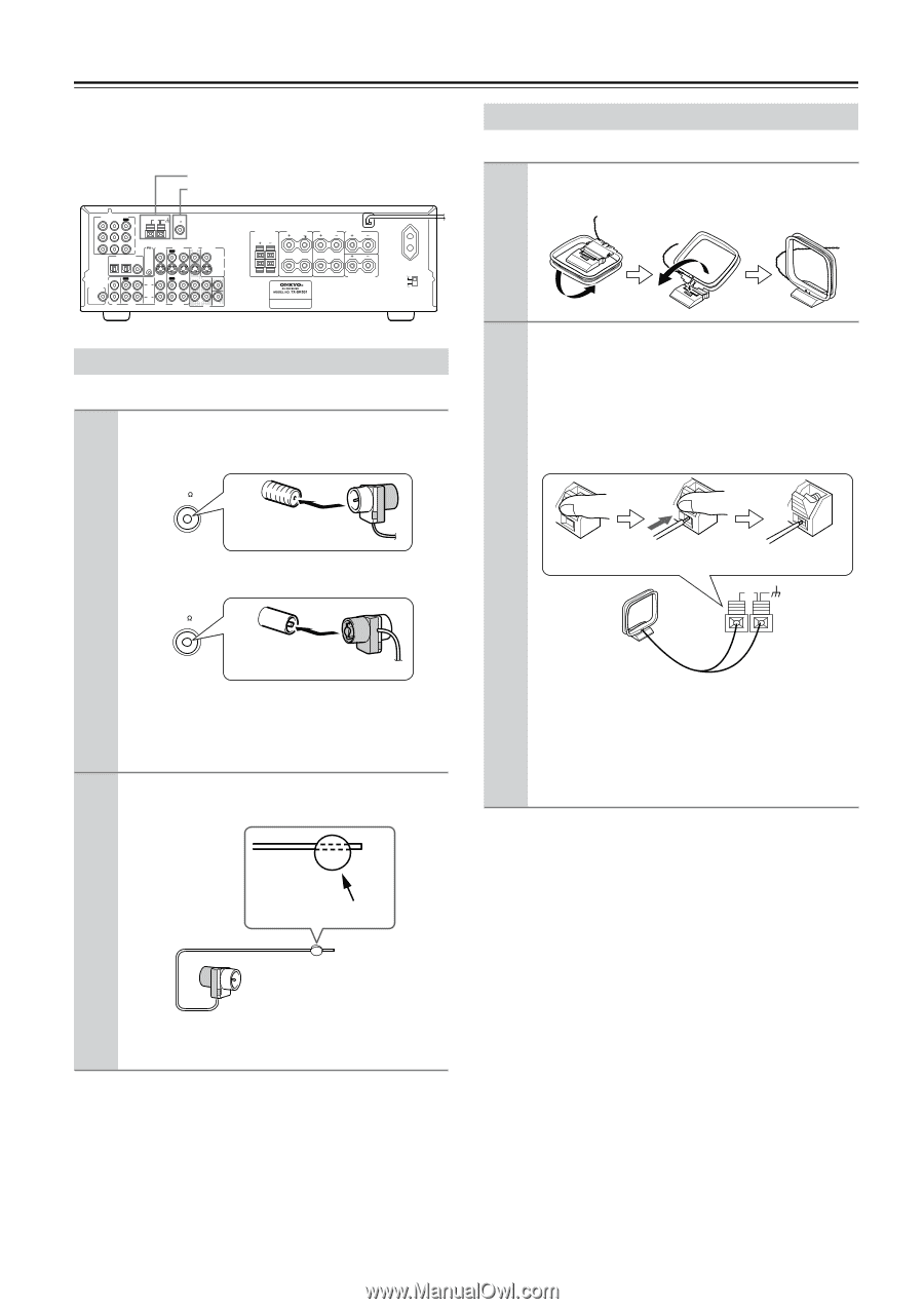
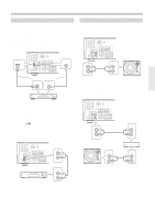
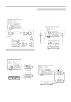
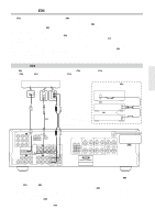
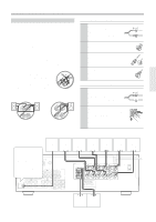
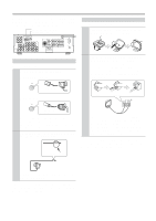
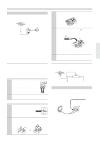
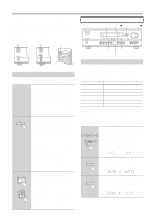
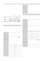
Connecting Antenna This chapter explains how to connect the supplied indoor FM antenna and AM loop antenna, and how to connect commercially available outdoor FM and AM antennas. AM antenna push terminals FM antenna connector COMPONENT VIDEO ANTENNA VIDEO 1 / 2 / 3 DVD IN IN OUT AM FM 75 Y PB PR DIGITAL INPUT OPTICAL COAXIAL 2 1 REMOTE CONTROL VIDEO 2 IN VIDEO 1 OUT IN DVD MONITOR IN OUT VIDEO S VIDEO IN OUT IN L SUBWOOFER PRE OUT R CD TAPE IN OUT IN FRONT SURR CENTER L L R VIDEO 2 VIDEO 1 R DVD SUB WOOFER FRONT SPEAKERS B FRONT SPEAKERS A L SURROUND SPEAKERS L CENTER SPEAKER AC OUTLET SWITCHED 100W MAX. L R R R SURROUND BACK SPEAKER VOLTAGE SELECTOR 120 V 220-230 V Connecting the Indoor FM Antenna The supplied indoor FM antenna is for indoor use only. 1 Attach the FM antenna, as shown. ■ North American Model FM 75 Insert the plug fully into the socket. ■ Other Models FM 75 Insert the plug fully into the socket. Once your TX-SR501/TX-SR501E is ready for use, you'll need to tune into an FM radio station and adjust the position of the FM antenna to achieve the best possible reception. 2 Use thumbtacks or something similar to fix the FM antenna into position. Connecting the AM Loop Antenna The supplied indoor AM loop antenna is for indoor use only. 1 Assemble the AM loop antenna, inserting the tabs into the base, as shown. 2 Connect both wires of the AM loop antenna to the AM push terminals, as shown. (The antenna's wires are not polarity sensitive, so they can be connected either way around). Make sure that the wires are attached securely and that the push terminals are gripping the bare wires, not the insulation. Push Insert wire Release AM Once your TX-SR501/TX-SR501E is ready for use, you'll need to tune into an AM radio station and adjust the position of the AM antenna to achieve the best possible reception. Keep the antenna as far away as possible from your TX-SR501/TX-SR501E, TV, speaker cables, and power cords. If you cannot achieve good reception with the supplied indoor AM loop antenna, try using it with a commercially available outdoor AM antenna (see page 23). Thumbtacks, etc. Caution: Be careful that you don't injure yourself when using thumbtacks. If you cannot achieve good reception with the supplied indoor FM antenna, try a commercially available outdoor FM antenna instead (see page 23). 22
-
 1
1 -
2
-
3
-
4
-
5
-
6
-
7
-
8
-
9
-
10
-
11
-
12
-
13
-
14
-
15
-
16
-
 17
17 -
 18
18 -
 19
19 -
 20
20 -
 21
21 -
 22
22 -
 23
23 -
 24
24 -
 25
25 -
 26
26 -
 27
27 -
28
-
29
-
30
-
31
-
32
-
33
-
34
-
35
-
36
-
37
-
38
-
39
-
40
-
41
-
42
-
43
-
44
-
45
-
46
-
47
-
48
 |
 |