Panasonic CF-19CDBAXVM Service Manual
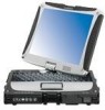
Panasonic CF-19CDBAXVM - Toughbook 19 Tablet PC Version Manual
 |
UPC - 092281864785
View all Panasonic CF-19CDBAXVM manuals
Add to My Manuals
Save this manual to your list of manuals |
Panasonic CF-19CDBAXVM manual content summary:
- Panasonic CF-19CDBAXVM | Service Manual - Page 1
ORDER NO. CPD0612203A1 Notebook Computer Model No. CF-19CDBAXVM This is the Service Manual for the following areas. M ...for U.S.A. and Canada © 2006 Matsushita Electric Industrial Co., Ltd. All rights reserved. Unauthorized copying and distribution is a violation of law. - Panasonic CF-19CDBAXVM | Service Manual - Page 2
1 - Panasonic CF-19CDBAXVM | Service Manual - Page 3
2 - Panasonic CF-19CDBAXVM | Service Manual - Page 4
3 - Panasonic CF-19CDBAXVM | Service Manual - Page 5
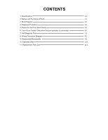
CONTENTS 1. Specifications 2. Names and Functions of Parts 3. Block Diagram 4. Diagnosis Procedure 5. Power-On Self Test (Boot Check) 6. List Test 8. Wiring Connection Diagram 9. Disassembly/Reassembly 10. Exploded View 11. Replacement Parts List 1-1 2-1 3-1 4-1 5-1 6-1 7-1 8-1 9-1 10-1 11-1 - Panasonic CF-19CDBAXVM | Service Manual - Page 6
Specifications Main Specifications Model No. CF-19CHBAXBM CF-19CDBAXVM CPU Intel® Core™ Duo Processor U2400 (1.06 GHz, 2 MB*1 L2 cache, 533 MHz FSB) Chipset Memory*1*2 Video Memory High DeÞnition Audio subsystem support, Monaural speaker TPM (TCG keys / Touch Pad / Digitizer (Anti-Reßec- Re - Panasonic CF-19CDBAXVM | Service Manual - Page 7
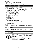
start] - [Run] and input "c:\util\drivers\tpm\README.pdf", and refer to the Installation Manual of "Trusted Platform Module (TPM)". *10 When using ExpressCard/34, the card slot cover cannot be closed. *11 Operation has been tested and conÞrmed using Panasonic SD Memory Cards with a capacity of up to - Panasonic CF-19CDBAXVM | Service Manual - Page 8
instruction manual of the wireless device. : Caps lock : Numeric key (NumLk) : Scroll lock (ScrLk) : Hard disk drive status F: Tablet Buttons Reference Manual "Tablet Buttons" G: LCD Reference Manual "Touchscreen" Reference Manual - Panasonic CF-19CDBAXVM | Service Manual - Page 9
Devices" D: Modem Port Reference Manual "Modem" E: LAN Port Reference Manual "LAN" F: SD Memory Card Indicator (Blinking: During access) Reference Manual "SD Memory Card" G: SD Memory Card Slot Reference Manual "SD Memory Card" H: Wireless Switch Reference Manual "Wireless Switch Utility" I: PC Card - Panasonic CF-19CDBAXVM | Service Manual - Page 10
Extension Memory PC2-3200 2GB RJ11 Data Modem MDC 1.5 AMP Sound Sigmatel STAC9200 Speaker Headphone Ext. MIC Wireless LAN 34945ABG 802.11 A/B/G antenna ExpressCARD PCMCIA R5C843 / 851 RICOH SmartCard(R5C851) SD slot RTL8101L Realtek TYPE II RJ45 Finger Print Digitizer Configuration - Panasonic CF-19CDBAXVM | Service Manual - Page 11
4 Diagnosis Procedure 4.1. Basic Procedures 4-1 - Panasonic CF-19CDBAXVM | Service Manual - Page 12
to start , No display on screen , etc. 2. Explanation of each trouble, mainly symptom of trouble in operation. Flow Chart SSTTAARRTT Pay attention to the following points when in pursuit of the cause of a troubleshooting. 1. Peripheral apparatus connected with the set should all be removed before - Panasonic CF-19CDBAXVM | Service Manual - Page 13
beep sound or error code. Start Test begins automatically when power switch is set to ON. Normal finish .....After memory checking, a beep sound is issued once and the set is placed into automatic stop. Note: If no error offering (Note) A beep sound is also issued in case of other I/O trouble. 5-1 - Panasonic CF-19CDBAXVM | Service Manual - Page 14
information about a hardware device, e.g., the amount of memory installed. Others may indicate a problem with a device, such as the way it has check the system battery or contact Panasonic Technical Support. 0260 System timer error The timer test failed. Requires repair of system board. 0270 Real - Panasonic CF-19CDBAXVM | Service Manual - Page 15
- Cache disabled Contact Panasonic Technical Support. 02F0: CPU ID: CPU socket number for Multi-Processor error. 02F4: EISA CMOS not writable ServerBIOS2 test error: Cannot write to EISA CMOS. 02F5: DMA Test Failed ServerBIOS2 test error: Cannot write to extended DMA (Direct Memory Access) registers - Panasonic CF-19CDBAXVM | Service Manual - Page 16
the DIAG program cannot perform HDD test. *This key is for service purpose only. Do not disclose this information to unrelated others. 1. the computer is turned on. 2. " F2 " is pushed on the screen of "Panasonic" while " press " is displayed. 3. The setup utility part. 7-1 - Panasonic CF-19CDBAXVM | Service Manual - Page 17
PC-Diagnostic Utility -Only the device which can be inspected on the entire screen is displayed. -The item does not appear when the device of wireless LAN etc. is not physically connected. -The movement of the item must use an arrow key or a flat pad. -As for the device under the - Panasonic CF-19CDBAXVM | Service Manual - Page 18
To test only a specific device, "Test" of the user 1. Turned on the computer. 2. "F2" is pushed on the screen while "Pressto enter Setup" is displayed of "Panasonic". 3. Push from RAM test when the memory is increased according to the performance of the memory occasionally. Moreover, when the - Panasonic CF-19CDBAXVM | Service Manual - Page 19
on "R.S.T . technology". Content of enhancing test Place with possibility of breakdown CPU / Main board Memory / Mainboard HDD MODEM Wireless LAN Sound *5 USB The record area frequently accessed with Microsoft Windows XP to test in about two minutes regardless of points of HDD is emphatically - Panasonic CF-19CDBAXVM | Service Manual - Page 20
connection of Main board and Wireless WAN module. It is confirmed PC which uses main memory as VRAM may fail with main memory failure. It is failure of cable characteristic and device problems. *8 It is confirmed not When the test result is PASS, trouble is thought by not hearing of the - Panasonic CF-19CDBAXVM | Service Manual - Page 21
PCB CN21 CN12 MODEM PCB LAN PORT SD PCB CN891 CN11 HDD MAIN BATTERY PCMCIA UNIT POWER SW PCB CN980 CN15 CN4 CN23 CN15 LANAUX WIRELESS MODULE J1 ANT PCB PAD PCB CN806 CN804 TOUCH PAD CN800 RIGHT LED PCB CN841 SW PCB CN950 HDD FPC BAT GPRS CN805 CN801 CN802 - Panasonic CF-19CDBAXVM | Service Manual - Page 22
Instructions 9.1.1. Preparation Before disassembling, be sure to make the following preparations. • Shut down Windows and turn off the power. • Disconnect the AC adaptor. • Remove the optional DIMM memory and Heat Spreader cannot be recycled. Use new parts. 9.1.2. Removing the Battery Pack and HDD - Panasonic CF-19CDBAXVM | Service Manual - Page 23
1 2 10. Disconnect the Cable from Connector (CN800). 11. Remove the Touch Pad and Click Button Plate. Screws : DFHE5025XA Screws : DRSB2+5FKL 9.1.4. Removing the DIMM Lid Ass'y DIMM Lid Ass'y Keyboard 4. Lift the far side of the Keyboard and slide - Panasonic CF-19CDBAXVM | Service Manual - Page 24
9.1.6. Removing the DU Lid Unit DIMM Lid Angle DU Lid Bluetooth PCB Antenna Cable(blue) HSDPA PCB Connector(CN1) Plate Clamper Connector(CN604) 1. Remove the 7 Screws . 2. Remove the DU Lid Angle and DU Lid. Screws : - Panasonic CF-19CDBAXVM | Service Manual - Page 25
PCB and Modem PCB Connector(CN8) HDD Connector Guide Connector(CN21) SD PCB Ass'y BAT FPC Ass'y Connector(CN17) Note: This procedure is not necessary if the computer is not equipped with Wireless Module or Modem PCB. 1. Disconnect the 2 LCD Cables. (CN8,CN17 - Panasonic CF-19CDBAXVM | Service Manual - Page 26
14. Remove the 2 Screws , and remove the DIMM Holder. Tape Connector(CN9) Connector(CN14) Screws : DFHE5058ZB Screws : DRSB2+5FKL 9.1.11. Removing the Power SW PCB Connector(CN9) Power SW PCB Connector(CN23) Main PCB Combo Socket 15. - Panasonic CF-19CDBAXVM | Service Manual - Page 27
9.1.13. Removing Pad PCB and SW PCB Pad PCB Connector(CN807) Connector(CN805) 9.1.14. Removing the Display unit LCD Hinge Cover 1. Disconnect the 2 Cables from the 2 Connectors (CN805,CN807). 2. Remove the 4 Screws . 3. Remove the Pad PCB. 1. Remove - Panasonic CF-19CDBAXVM | Service Manual - Page 28
9.1.15. Removing the LCD Rear Case LCD Rear Case Antenna Cover Tablet Latch Cover Antenna Cover 1. Remove the 8 Screws on the - Panasonic CF-19CDBAXVM | Service Manual - Page 29
9.1.19. Removing the Each Cover DC IN LID Rubber USB LID Rubber LAN LID Rubber Moden/LAN LID Rubber Battery LID ASS'Y HDD LID ASS'Y Audio LID Rubber USB Back Rubber RGB LID Rubber Serial LID Rubber PCMCIA - Panasonic CF-19CDBAXVM | Service Manual - Page 30
Instructions 9.2.1. Attention when CF-19 series is repaired • Please execute writing BIOS ID when you exchange the Main Board. • Parts (Sheet and rubber) etc. related various the Conductive Cloth and Heat Spreader cannot be recycled. Use new parts fix them together. Screw Detail of "A" A 0 3mm - Panasonic CF-19CDBAXVM | Service Manual - Page 31
Model : Digitizer Model) 0 0.5mm PCB Attch to the side surface of the Frame. Match to the end of the Frame within 0 to 0.5 mm at the far side. Screw the Board together PCB n Assembly of Inverter PCB 0 0.5mm 0 0.5mm 0 0.5mm 0 0.5mm 2 0.5mm 10 2mm 0 0.5mm 0 0.5mm Important Parts for Safety - Panasonic CF-19CDBAXVM | Service Manual - Page 32
. 0 1mm The gap side is front. Safety Working 0 1mm LCD Ass'y Details of "A" Ensure the edge of the conductive fabric is not frayed. 1 2 the Avoid any stress on the Cable when connecting it. Hold the Connector part when connecting/disconnecting. LCD Cable TS middle of right and left. Attach the - Panasonic CF-19CDBAXVM | Service Manual - Page 33
Assembly of Inverter PCB (Application Model : Digitizer Model) Inverter Ass'y LCD Back Dumper Conductive Protect Sheet Attach it to the front side. (Using the jig) Dimensional tolerance: 0.2 T/S A Details of "A" Back Side 6 0.5mm TS FPC Spacer 0 0.5mm Touch Screen TS Spacer A Match to - Panasonic CF-19CDBAXVM | Service Manual - Page 34
n Assembly of Glass (Applicable Model : Digitizer Model) 9.2.3. Assembling the WWAN Main Antenna PCB, LAN-Main BT Antenna PCB, LAN AUX Antenna PCB, WWAN AUX Antenna PCB and Pen holder 1. Fix the - Panasonic CF-19CDBAXVM | Service Manual - Page 35
running over the rib, etc.. Screw Put the Cable on each hook Screw LAN-AUX ANT Screw Match to the edge of Cabinet Safety Working Details of "D" Match to the edge of Cabinet A Cable Cushion Attachment Method (3 Places) Bundle and wind 3 antenna cables. Safety Working Insert it between the wall and - Panasonic CF-19CDBAXVM | Service Manual - Page 36
the Cable. If you arrange the Cable in the area, you do not need to use the fixing jig. Screw Avoid catching the Cable (when repairing or when not using the jig). Temporarily fix the both sides ("A") of the Hinge using the Screw, and fix the Cable Hold Plate. After fixing - Panasonic CF-19CDBAXVM | Service Manual - Page 37
'y Magnet Tape 0 1mm 0 0.5mm Magnet 1mm (Both on the top and the side) Avoid running over Tape Note for attachment Avoid running over the display part. Attach and apply the load 30 to 40N (3.0 to 4.0 Kgf). Attach here Position of pasting D. 0 0.5mm 0 0.5mm Fit to the rib 0 0.5mm 9-16 - Panasonic CF-19CDBAXVM | Service Manual - Page 38
Rear Cushion E n Assembly of LCD Rear Case (Applicable Model : Digitizer Model) (Note) Arrow without specified measurement: 0 to 0.5 mm Rear Cushion C LCD Rear Ass'y Marking line 0.5mm Safety Working Important Parts for Safety Safety critical component LCD Rear Cushion C Marking line 0.5mm LCD - Panasonic CF-19CDBAXVM | Service Manual - Page 39
n Assembly of Tablet Latch Cover and Antenna Cover Press and hold it against the cabinet, Tablet Lacth Cover and fix it using the Screw. Antenna Cover Press and hold it against the cabinet, and fix it using the Screw. Screw Locations Screw 10 Places Screw 16 Places Fix in the order. the front - Panasonic CF-19CDBAXVM | Service Manual - Page 40
9.2.6. Setting the Display Unit 1. Fix the Display Unit using the 2 Screws . 2. Close the Display Unit and turn the computer over, then fix the Display Unit using the 4 Screws . 3. Turn the computer over and fix the LCD Hinge Cover using the 2 Screws . - Panasonic CF-19CDBAXVM | Service Manual - Page 41
n Assembly of Display Unit Details of "A" Safety Working Note Avoid any stress on the Cable. Pass the Cable through the groove. Note: Running over affects the waterproof performance.. Black/White - Panasonic CF-19CDBAXVM | Service Manual - Page 42
9.2.7. Setting the Pad PCB and SW PCB 1. Attach both the SW PCB and the Operation Sheet to the Cabinet. SW PCB 2. Connect the 3 Cables to the 3 Connectors. (CN800,CN805,CN807) 3. Fix the Pad PCB using the 4 Screws. Note: Tighten the Screws in the numbered order (No1 to No4). Screws : - Panasonic CF-19CDBAXVM | Service Manual - Page 43
it. Ensure that the direction is right when attaching. The Connector bracket is on the back side. Avoid coming off of the LED part, or running over the LED part. SW PCB Operation Sheet n Putting of the TP Bottom Tape Front side SW PCB Ass'y Match to the upper left corner. 0 to - Panasonic CF-19CDBAXVM | Service Manual - Page 44
right LED PCB LED(L) PCB Ass'y LED PCB(L) LED Light Guide Sheet(L) Match the edge and attach it. Avoid running over the N1> Screws : DFHE5025XA LED(R) PCB Ass'y Match the edge and attach it. LED Light Guide Sheet(R) LED PCB(R) LED PWB Tape(R) Match the edge and attach it. Connector(CN9) - Panasonic CF-19CDBAXVM | Service Manual - Page 45
using the 4 Screws. Screws : DFHE5058ZB Screws : DRSB2+5FKL I/O PCB Ass'y 9.2.11. Setting the Main PCB, Wireless Module, SD PCB, DU PCB, Antenna PCB and Modem PCB 1. Fix the Main PCB using the 7 Screws . 2. Connect the 3 Cables to the 3 Connectors - Panasonic CF-19CDBAXVM | Service Manual - Page 46
the Cable to the Connector (CN3) and attach the Coin Battery. DIMM Holder Wireless Module Connector(CN3) Connector. (CN15) 13. Fix the HDD Connector Guide using the 2 Screws . HDD Connector Guide Connector(CN21) - Panasonic CF-19CDBAXVM | Service Manual - Page 47
14. Fix the DU PCB and the Plate using the 2 screws . 15. Fix the DU PCB Ass'y and Antenna PCB using the 3 screws and the 2 screws . 16. Connect the white, black and gray Cables. DU PCB Antenna PCB Plate 17. Turn the computer over, open the - Panasonic CF-19CDBAXVM | Service Manual - Page 48
n Assembly of Main PCB Process in the order of 1 2 3 4. MDC Basteraid 0 1mm 0 1mm Modem Tape Modem Cable Connect to the MDC connector. Fold the Tape in half. Fold back Basteraid 0 1mm 0 1mm Cover the Screw head If one screw is supplied, insert into the DIMM lower slot. MODEM PCB Set If two - Panasonic CF-19CDBAXVM | Service Manual - Page 49
Match to the edge of the Board. 0 to 1mm Insulation Tape Back side Fold back and attach it Match to the Connector. 0 to 1 mm Remove the DIMM and attach the Sheet. Set the DIMM after attaching the Sheet. DIMM Sheet Match to the silk 0 0.5mm Match to the silk 0 0.5mm DIMM Sheet Match to the - Panasonic CF-19CDBAXVM | Service Manual - Page 50
second. Screw (Note for spraying around when applying.) Connect Main PCB Ass'y Details of the LAN/MODEM Screw Screw Round to make the brown side outside module to the notch Wireless Module Screw Screw Screw Safety critical componentInsert and then lock. Important Parts for Safety Insert the - Panasonic CF-19CDBAXVM | Service Manual - Page 51
Ensure that both top and bottom are hooked. Screw Slide the Battery FPC Ass'y Screw Battery FPC Ass'y Insert the end of the Sheet into the space between the Main Board and the bottom of the PCMCIA Slot. (Left and Right 0.5mm, Apply 20 to 30N (2.0 to 3.0 Kgf)) Attach it fitting to the right. 0 0. - Panasonic CF-19CDBAXVM | Service Manual - Page 52
9.2.13. Setting the HSDPA PCB and Bluetooth PCB 1. Fix the Plate and Bluetooth PCB using the 2 Screws . 2. Connect the Cable to the Connector. (CN1) 3. Connect the Cable to the Connector. (CN604) 4. Fix the Plate and the Board using the 4 Screws . 5. Attach the blue Antenna Cable to - Panasonic CF-19CDBAXVM | Service Manual - Page 53
n Line Processing of Antenna Cable of Main Unit Cable Process 1/3 Step 1 Place brown/blue/gray cables at left and white/black cables downward. Step 3 After connecting the black antenna cable, connect it into the Holder as illustrated. Put the surplus under along the rib. Step 2 After - Panasonic CF-19CDBAXVM | Service Manual - Page 54
Cable Process 3/3 Step 12 Connect the brown antenna cable. Step 13 Step 14 Cable Holder Cushion Insert it into the boss. (Push it downward from the top of boss.) Cable Connect the additional cable (black). 9.2.14. Assembling the DU Lid Unit 1. Fix the DU Lid Angle and the DU Lid using the 7 - Panasonic CF-19CDBAXVM | Service Manual - Page 55
the circles. 0 to 1mm Match to the wall. 0 to 1mm Match to the wall. 0 to 1mm 0 1mm Tape Potre Blind Sheet Rated Label Important Parts for Safety Safety critical component Note for attachment Avoid running over the frame. Avoid air leaking into it. Bottom Rubber Bottom Case Assy Bottom Rubber - Panasonic CF-19CDBAXVM | Service Manual - Page 56
9.2.17. Setting the Touch Pad and Keyboard 1. Connect the Cable to the Connector (CN800), and attach the Touch Pad to the computer. 2. Set the Click Button Plate. 3. Attach the new TP Tape over the Touch Pad. 4. Attach the Palm Rest Ass'y on the computer. Keyboard Keyboard FPC TP Tape 7. Set the - Panasonic CF-19CDBAXVM | Service Manual - Page 57
Because the sheets described on this page are waterproof sheets, the whole parts should be put pressure after attaching. (Especially, put pressure around the Screw Screw Screw Screw Screw Connect the LCD CABLE KBD FFC insert parts Screw Screw Screw Incline to the right. Avoid running over the - Panasonic CF-19CDBAXVM | Service Manual - Page 58
n Putting of the Palm Rest ASSY 3 5mm 6 8mm Windows Logo Label Intel Label 5 7mm 6 8mm Energy Star Label 4 6mm Remove the Release Paper, and then attach the Palmrest Assy. Remove the two-sided tape - Panasonic CF-19CDBAXVM | Service Manual - Page 59
9.2.18. Setting the Battery Pack and the HDD Pack 1. Set the HDD in the HDD Case and fix it using the 2 Screws. HDD Case B HDD FPC Hooks HDD Hooks Heater 2. Open the HDD Cover and set the HDD Pack. 3. Open the Battery Cover and set the Battery. Screws : DXQT2+D4FNL - Panasonic CF-19CDBAXVM | Service Manual - Page 60
width x 4 cm) Heater Insulation Sheet Attach on the inside of 1 Details for attachment of Heater Insulation Sheet 0 0.5mm Note for the Heater top end location 0 1mm Insulation Parts 10 15mm Avoid any stress Insulation Parts Heater Assy 5 1mm Back 5 1mm HDD Connect the Connector Round to - Panasonic CF-19CDBAXVM | Service Manual - Page 61
9.2.19. Assembling the Each Cover 1. Fix the Battery LID Ass'y, the HDD LID Ass'y, and the PCMCIA LID Ass'y using the 6 Screws. 2. Set the Rear Cabinet. 3. Fix the Modem/LAN LID Rubber, the LAN LID Rubber, the USB LID Rubber, the DC IN LID Rubber, the Serial LID Rubber, the RGB LID Rubber, - Panasonic CF-19CDBAXVM | Service Manual - Page 62
torque A 0.2 +_ 0.02N m (2.0 +_ 0.2kgf cm) F 0.8 +_ 0.02N m (8.0 +_ 0.2kgf cm) K80-9 K80-6 K80-5 K80-7 K80-8 K80-11 K80-10 K80-8 E23 K80-2 10-1 F N11 K80 K80-1 K80-4 K80-3 CF-19CDBAXVM - Panasonic CF-19CDBAXVM | Service Manual - Page 63
-13-2 A K12-13-9 K12-13-7 K12-13-1 K12-13-6 K12-13-3 B K12-13-10 K12-13-1 B K12-16 K12-16 K12-3-5 B K12-3-10 K12-3-4 10-2 CF-19CDBAXVM - Panasonic CF-19CDBAXVM | Service Manual - Page 64
A N9 A A N9 K126 K92 A N1 A N1 K36 A N1 A N1 K43 E4 A N1 E31 K42 A N1 Screw tightening torque A 0.2 +_ 0.02N m (2.0 +_ 0.2kgf cm) H 0.4 +_ 0.02N m (4.0 +_ 0.2kgf cm) 10-3 CF-19CDBAXVM - Panasonic CF-19CDBAXVM | Service Manual - Page 65
-1 K14-1-2 K16 A N10 K16 A N10 N10 A N10 A K16 A N10 A N10 K1 K14-1-1 A K14-8 A K14-8 K85 K84 N6 N6 Screw tightening torque A 0.2 +_ 0.02N m (2.0 +_ 0.2kgf cm) 10-4 CF-19CDBAXVM - Panasonic CF-19CDBAXVM | Service Manual - Page 66
K10-4-1 K10-4 K10-4-4 K10-4-1-1 K10 K10-4-3 K61 K62 E36 K61 K10-4-4 A N1 A N1 A N1 K10-4-3 A N1 K29 K6 K63 K10-1-6 K10-1-7 E17 K10 -1-5 K101-3 E16 K10-4-5 K8 K52 K79 K58 K7 K70 D N17 K79 K58 D N17 K66 K10-2 K10-3 A K10-1-13 K10-1-11 K10-1-7 K10-1-6 K10-1-9 K67 K59 K57 K59 - Panasonic CF-19CDBAXVM | Service Manual - Page 67
E36 A E36-7 K73 K72 K76 K74 K78 K65 E22 K77 E21 E36-6 E36-4 E36-1-2 E36-1-1 E36-1 A E36-7 K54 E36-21 E36-22 E36-9 E36-23 E36-22 A E36-7 E36-20 E36-9 E36-22 E36-11 E36-12 E36-11 A E36-7 E36-10 K71 Screw tightening torque A 0.18 +_ 0.02N m (1.8 +_ 0.2kgf cm) 10-6 C F -19C DB AXV - Panasonic CF-19CDBAXVM | Service Manual - Page 68
K68 C N7 C N7 K69 C N7 C N7 C N7 C N7 C N7 B N15 K11 K11-1 K11-6 K11-8 K11-1-3 K11-1-1 K11-1-5 K11-1-4 K11-1-2 C N7 B N15 K11-10 K11-1-3 K11-1-1 K11-5 K11-6 K11-7 K11-1-4 K11-8 K11-6 K11-1-5 K11-2 K11-3 K11-2 K11-3 K11-2 K11-5 Screw tightening torque B 0.2 +_ 0.02N m (2.0 _+ - Panasonic CF-19CDBAXVM | Service Manual - Page 69
parts. CF-19CDBAXVM (2006/11/20) REF. NO and AREA PART SODIMM 512M INFINEON WLAN COAXIAL CABLE WIRELESS LAN MODULE THERMISTOR POWER SW CABLE TOUCHPAD SIDE LCD SIDE CUSHION A LCD SIDE CUSHION C LCD SIDE CUSHION D DIGITIZER SHEET LCD LIGHT SHIELD SHEET B ADHESIVE TAPE(PG SIDE) Q'TY RTL - Panasonic CF-19CDBAXVM | Service Manual - Page 70
AC CORD 1 A4 S DFQX5624ZA MANUAL(CF-19MK1) 1 A5 DFJS954ZA MODEM CABLE 1 A6 DFHS9017ZA TOUCHPANEL FUKINUNO 1 Packing Material P1 DFPE0733YA HOLDER 1 P2 DFPE0859YA HOLDER 1 P3 DFPK1210ZA PACKING CASE 1 P4 DFPK1216YA ACCESSORY BOX 1 Mechanical Parts K1 DFHM9017ZA-0 EZC - Panasonic CF-19CDBAXVM | Service Manual - Page 71
LCD REAR CUSHION D 1 K11-8 DFHR3565YA LCD REAR CUSHION E 2 K11-9 DFGB0132ZA-0 TOUGH BOOK BADGE(SILVER) 1 K11-10 DFGB0131ZA-0 PANASONIC BADGE 1 K12 S DFKM9040ZA-0 TOP CASE ASSY 1 K12-1 DFHM0320YA TOP ELEPASS 2 K12-2 DFHR3434ZA AUDIO WATERPROOF SHEET 1 K12-3 DFHR3440ZA - Panasonic CF-19CDBAXVM | Service Manual - Page 72
1 K14-7 DFUS0316ZA PLATE SPRING GUIDE PIN 2 K14-8 DRHM5025YAT SCREW 1 K30 DFHM0302XA-2 KEYBOARD PLATE(L) CF-19 1 K31 DFHM0303XA-0 KEYBOARD 1 K45 DFHR6246ZA HDD GUIDE 1 K46 DFHR6284ZA DIMM GUIDE SHEET 1 K52 DFWV91J0031 DIGITIZER PEN ASS'Y 1 K52-1 DFHR6309ZA DIGITIZER - Panasonic CF-19CDBAXVM | Service Manual - Page 73
1 K80-5 DFHR3F54ZA HDD CON SHEET 1 K80-6 DFHR6297ZA HDD CONNECTOR GUARD 1 K80-7 DL3UP1564AAA HDD FPC UNIT 1 K80-8 DFMX0383TA INSULATION PARTS 2 K80-9 DFMX1265ZA INSULATION SHEET(HDD HEATER) 1 K80-10 DFMY3208ZA THERMAL SHEET 1 K80-11 S L9DZYY000008 HEATER(HDD) 1 K81 - Panasonic CF-19CDBAXVM | Service Manual - Page 74
K106 DFHR3049ZA LCD DAMPER E 1 K107 DFHR3438ZA CLICK BUTTON SHEET 1 K108 DFHR3483SA OPERATION SHEET 1 K109 DFHR3583YA KB WP SHEET 1 K110 DFHR3642YA LCD CUSHION SHEET 2 K111 DFHR3643ZA TP BOTTOM TAPE 1 K112 DFHR3655YA HDD CASE SPACER 2 K113 DFHR3D90ZA KB CNT HOLE CUSHION - Panasonic CF-19CDBAXVM | Service Manual - Page 75
identified by ! mark have special characteristics important for safety. When replacing any of these components use only manufacturer's specified parts. CF-19CDBAXVM (2006/11/20) REF. NO and AREA PART NO. MAIN PCB C 1, 2, 3, 6, 7, 8, 10, 11, 12, 14, 15, 16, 18, 19, 20, 22, 23, 24, 27, 28, 29, 30 - Panasonic CF-19CDBAXVM | Service Manual - Page 76
CAPACITOR, 50V, 150pF 1 C 803 F1G1H331A496 CAPACITOR, 50V, 330pF 1 C 807 F1H1H1830001 CAPACITOR, 50V, 0.018µF 1 CF 1, 2, 3 D4CC1103A038 THERMISTOR 3 CN 2 K1MYL0B00003 CONNECTOR 1 CN 3, 904 K1KA02BA0014 CONNECTOR 2 CN 4 K1NAF0D00003 CONNECTOR 1 CN 5 K1KY42B00001 - Panasonic CF-19CDBAXVM | Service Manual - Page 77
IC, LOGIC 2 IC 23, 24, 25 C0EBE0000460 IC 3 IC 26 C0EBH0000457 IC 1 IC 27 C2CBJA000003 IC, MICON 1 IC 30 C3FBLY000024 IC, SPI FLASH MEMORY 1 IC 31 C1CB00002268 IC, SECURITY CHIP 1 IC 33, 51, 52, 59 C0JBAA000348 IC, 1 GATE LOGIC 4 IC 41, 58 C0JBAE000306 IC, 2 IC 42 - Panasonic CF-19CDBAXVM | Service Manual - Page 78
IC 600 C0ABZA000047 IC, AMP 1 IC 601 C0ABBA000093 IC, OP AMP 1 IC 602 C0DBAYY00194 IC, DC/DC 1 IC 603 C0JBAD000236 IC, LOGIC 1 IC 604 C0JBAB000622 IC, 1 GATE LOGIC 1 IC 605 C0DBEFH00002 IC, REGULATOR 1 IC 606 C0CBCAC00161 IC 1 IC 607 C0EBE0000333 IC 1 IC 608 - Panasonic CF-19CDBAXVM | Service Manual - Page 79
R 22 ERJ2RKF75R0X RESISTOR, 1/16W, 75Ω 1 R 23 ERJ2GEJ240X RESISTOR, 1/16W, 24Ω 1 R 26, 266, 609, 612, 613, 749 ERJ2GEJ562X RESISTOR, 1/16W, 5.6KΩ 6 R 27, 29 ERJ2RKF2210X RESISTOR, 1/16W, 221Ω 2 R 33, 34, 78, 132, 167 ERJ2RKF24R9X RESISTOR, 1/16W, 24.9Ω 5 R 37 ERJ2RKF2000X - Panasonic CF-19CDBAXVM | Service Manual - Page 80
R 267, 268, 269, 270 ERJ2RKF49R9X RESISTOR, 1/16W, 49.9Ω 4 R 273 EXBV8V750JV RESISTOR ARRAY 1 R 274, 275, 276, 640, 666, ERJ2GEJ223X RESISTOR, 1/16W, 22KΩ 6 R 28346, 285 D1H81024A024 RESISTOR ARRAY 2 R 290, 291 ERJ2GEJ222X RESISTOR, 1/16W, 2.2KΩ 2 R 311, 317, 436 ERJ2RKF3901X - Panasonic CF-19CDBAXVM | Service Manual - Page 81
X1 H0J143500058 OSCILLATOR, 14.318MHz 1 X2 H0J327200115 OSCILLATOR, 32.768KHz 1 X3 H0J245500083 XTAL 1 X4 H0J250500076 XTAL 1 X5 H2D800400015 OSCILLATOR, 8MHz 1 ZA 1, 2, 5, 6, 7, 10, 11 K1YGZZ000060 SPACER 7 AUDIO PCB C 900, 905, 910, 942, 943, F1H1A1050015 CAPACITOR, 10V, - Panasonic CF-19CDBAXVM | Service Manual - Page 82
C 883 F1L1E106A017 CAPACITOR, 25V, 10µF 1 C 884, 885, 886, 887, 888, F1G1H330A542 CAPACITOR, 50V, 33pF 7 889, 890 C 891 F1G1C104A042 CAPACITOR, 16V, 0.1µF 1 C 892, 893 EZASCE101M CAPACITOR ARRAY 2 CH 883 S DFJS1063ZA I/O DC CABLE 1 CN 880 K1MN24AA0058 CONNECTOR 1 CN 881 - Panasonic CF-19CDBAXVM | Service Manual - Page 83
CN 851 K1KAA0AA0244 CONNECTOR 1 L 852, 853 J0JJC0000015 INDUCTOR 2 L 850 J0MAB0000200 INDUCTOR 1 LED-RIGHT PCB CN 780 K1MN06AA0058 CONNECTOR 1 LD 781 B3AGB0000040 DIODE 1 LD 782 B3ADB0000065 DIODE 1 LD 783 B3ABB0000210 DIODE 1 SD PCB C 890 F1G1C104A042 CAPACITOR, 16V, - Panasonic CF-19CDBAXVM | Service Manual - Page 84
INDUCTOR 1 Q1 B1GBCFJN0037 TRANSISTOR 1 Q2 B1DHDC000028 TRANSISTOR 1 R 1, 2 ERJ2GEJ104X RESISTOR, 1/16W, 100KΩ 2 HDD FPC CF 1 D4CC1103A038 THERMISTOR 1 CN 1 K1KY42A00001 CONNECTOR 1 CN 2 K1KY22A00001 CONNECTOR 1 CN 3 K1KA04BA0014 CONNECTOR 1 BATTERY FPC CN
-
 1
1 -
 2
2 -
 3
3 -
 4
4 -
 5
5 -
 6
6 -
 7
7 -
8
-
9
-
10
-
11
-
12
-
13
-
14
-
15
-
16
-
17
-
18
-
19
-
20
-
21
-
22
-
23
-
24
-
25
-
26
-
27
-
28
-
29
-
30
-
31
-
32
-
33
-
34
-
35
-
36
-
37
-
38
-
39
-
40
-
41
-
42
-
43
-
44
-
45
-
46
-
47
-
48
-
49
-
50
-
51
-
52
-
53
-
54
-
55
-
56
-
57
-
58
-
59
-
60
-
61
-
62
-
63
-
64
-
65
-
66
-
67
-
68
-
69
-
70
-
71
-
72
-
73
-
74
-
75
-
76
-
77
-
78
-
79
-
80
-
81
-
82
-
83
-
84
 |
 |
ORDER NO.
CPD0612203A1
Notebook Computer
CF-19CDBAXVM
© 2006 Matsushita Electric Industrial Co., Ltd. All rights reserved.
Unauthorized copying and distribution is a violation of law.
This is the Service Manual for
the following areas.
M …for U.S.A. and Canada
Model No.