Panasonic CF-19CDBAXVM Service Manual - Page 27
Removing Pad PCB and SW PCB, 1.14., Removing the Display unit
 |
UPC - 092281864785
View all Panasonic CF-19CDBAXVM manuals
Add to My Manuals
Save this manual to your list of manuals |
Page 27 highlights
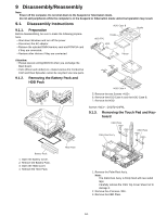
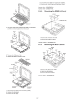
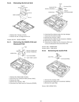
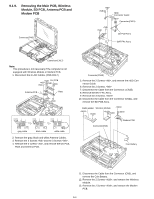
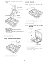
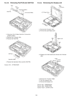
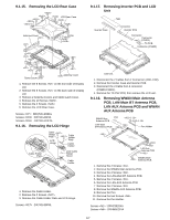
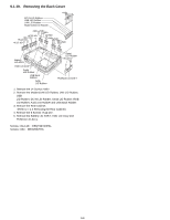
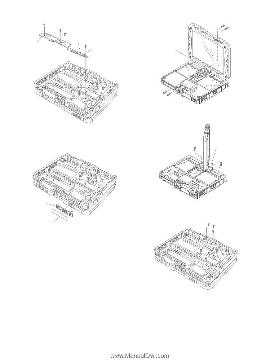
9.1.13. Removing Pad PCB and SW PCB Pad PCB Connector(CN807) Connector(CN805) 9.1.14. Removing the Display unit LCD Hinge Cover 1. Disconnect the 2 Cables from the 2 Connectors (CN805,CN807). 2. Remove the 4 Screws . 3. Remove the Pad PCB. 1. Remove the 4 Screws . 2. Remove the LCD Hinge Cover. Hinge Cover SW PCB Operation Sheet 4. Remove the Operation Sheet and the SW PCB. Screws : DFHE5025XA 3. Display unit is half-rotated and removes the 2 Screws . 4. Remove the 4 Screws . 5. Turn the computer over. 6. Remove the Display Unit. Screws : DFHE5025XA Screws : DRSB2+5FKL Screws : DXYN4+J7FNL 9-6
-
 1
1 -
2
-
3
-
4
-
5
-
6
-
7
-
8
-
9
-
10
-
11
-
12
-
13
-
14
-
15
-
16
-
17
-
18
-
19
-
20
-
21
-
 22
22 -
 23
23 -
 24
24 -
 25
25 -
 26
26 -
 27
27 -
 28
28 -
 29
29 -
 30
30 -
 31
31 -
 32
32 -
33
-
34
-
35
-
36
-
37
-
38
-
39
-
40
-
41
-
42
-
43
-
44
-
45
-
46
-
47
-
48
-
49
-
50
-
51
-
52
-
53
-
54
-
55
-
56
-
57
-
58
-
59
-
60
-
61
-
62
-
63
-
64
-
65
-
66
-
67
-
68
-
69
-
70
-
71
-
72
-
73
-
74
-
75
-
76
-
77
-
78
-
79
-
80
-
81
-
82
-
83
-
84
 |
 |
9-6
9.1.13.
Removing Pad PCB and SW PCB
1. Disconnect the 2 Cables from the 2 Connectors
(CN805,CN807).
2. Remove the 4 Screws <N1>.
3. Remove the Pad PCB.
4. Remove the Operation Sheet and the SW PCB.
Screws <N1> : DFHE5025XA
9.1.14.
Removing the Display unit
1. Remove the 4 Screws <N1>.
2. Remove the LCD Hinge Cover.
3. Display unit is half-rotated and removes the 2 Screws
<N9>.
4. Remove the 4 Screws <N18>.
5. Turn the computer over.
6. Remove the Display Unit.
Screws <N1> : DFHE5025XA
Screws <N9> : DRSB2+5FKL
Screws <N18> : DXYN4+J7FNL
<N1>
<N1>
<N1>
<N1>
Pad PCB
Connector(CN807)
Connector(CN805)
SW PCB
Operation Sheet
<N1>
<N1>
LCD Hinge Cover
<N1>
<N1>
<N9>
<N9>
Hinge Cover
<N18>
<N18>
<N18>
<N18>