Panasonic CF-19CDBAXVM Service Manual - Page 25
Removing the Main PCB, Wireless, Module, SD PCB, Antenna PCB and, Modem PCB
 |
UPC - 092281864785
View all Panasonic CF-19CDBAXVM manuals
Add to My Manuals
Save this manual to your list of manuals |
Page 25 highlights
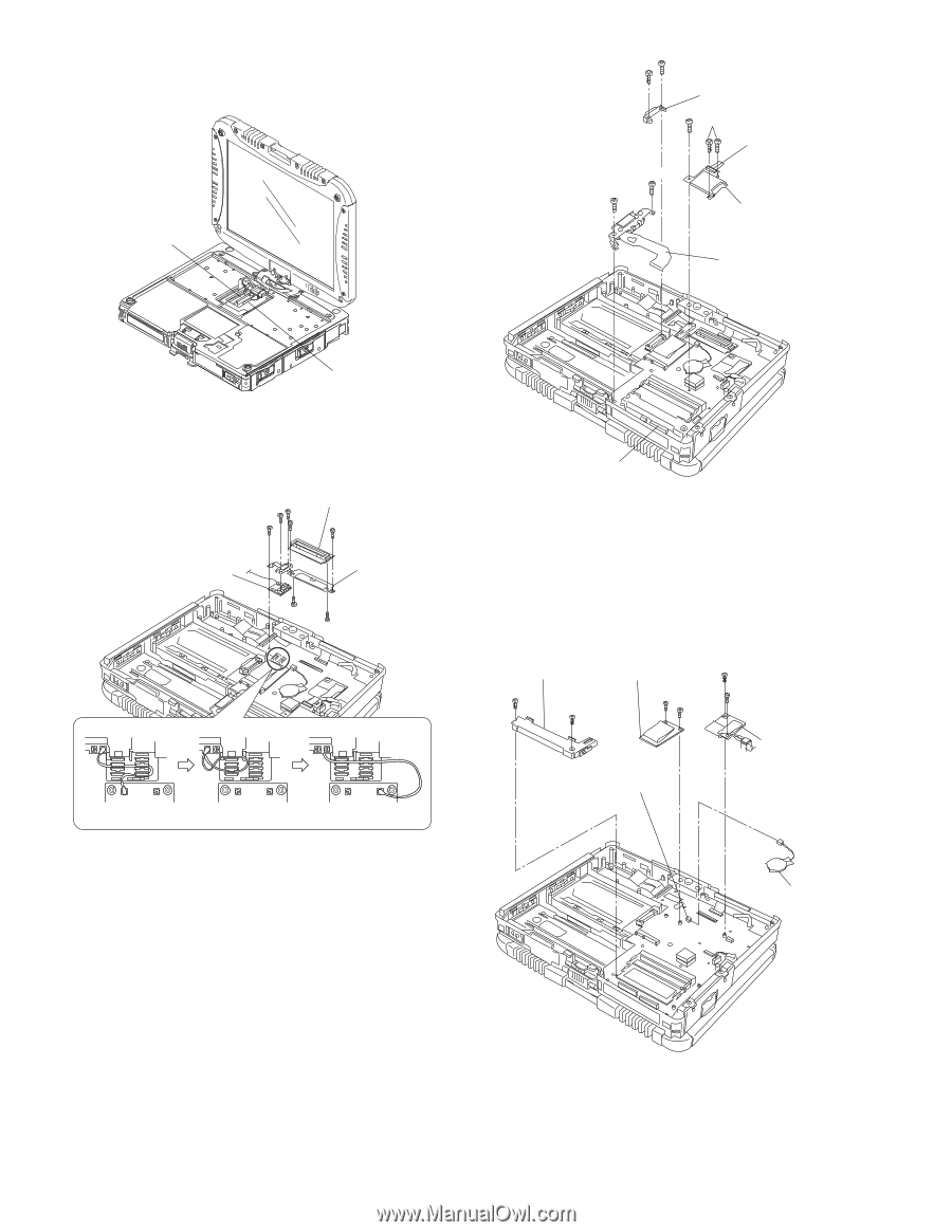
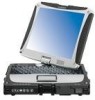
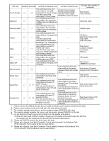
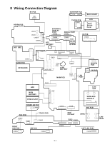
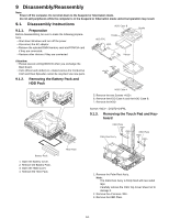
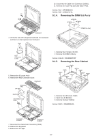
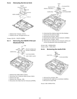
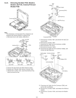
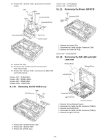
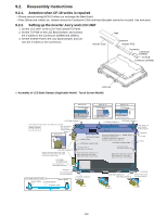
9.1.9. Removing the Main PCB, Wireless Module, SD PCB, Antenna PCB and Modem PCB Connector(CN8) HDD Connector Guide Connector(CN21) SD PCB Ass'y BAT FPC Ass'y Connector(CN17) Note: This procedure is not necessary if the computer is not equipped with Wireless Module or Modem PCB. 1. Disconnect the 2 LCD Cables. (CN8,CN17) DU PCB Antenna PCB Plate gray cable black cable white cable 2. Remove the gray, black and white Antenna Cables. 3. Remove the 2 Screws and the 3 Screws . 4. Remove the 2 screws , and remove the DU PCB, Plate and Antenna PCB. Connector(CN15) 5. Remove the 2 Screws , and remove the HDD Connector Guide. 6. Remove the 2 Screws. 7. Disconnect the Cable from the Connector. (CN15) 8. Remove the BAT FPC Ass'y. 9. Remove the 3 Screws. 10. Disconnect the Cable from the Connector (CN21), and remove the SD PCB Ass'y. DIMM Holder Wireless Module Connector(CN3) Modem PCB Coin Battery 11. Disconnect the Cable from the Connector (CN3), and remove the Coin Battery. 12. Remove the 2 Screws , and remove the Wireless Module. 13. Remove the 2 Screws , and remove the Modem PCB. 9-4
-
 1
1 -
2
-
3
-
4
-
5
-
6
-
7
-
8
-
9
-
10
-
11
-
12
-
13
-
14
-
15
-
16
-
17
-
18
-
19
-
 20
20 -
 21
21 -
 22
22 -
 23
23 -
 24
24 -
 25
25 -
 26
26 -
 27
27 -
 28
28 -
 29
29 -
 30
30 -
31
-
32
-
33
-
34
-
35
-
36
-
37
-
38
-
39
-
40
-
41
-
42
-
43
-
44
-
45
-
46
-
47
-
48
-
49
-
50
-
51
-
52
-
53
-
54
-
55
-
56
-
57
-
58
-
59
-
60
-
61
-
62
-
63
-
64
-
65
-
66
-
67
-
68
-
69
-
70
-
71
-
72
-
73
-
74
-
75
-
76
-
77
-
78
-
79
-
80
-
81
-
82
-
83
-
84
 |
 |