Panasonic CF-19CDBAXVM Service Manual - Page 32
Assembly of Inverter PCB Applicable Model : Touch Screen Model
 |
UPC - 092281864785
View all Panasonic CF-19CDBAXVM manuals
Add to My Manuals
Save this manual to your list of manuals |
Page 32 highlights
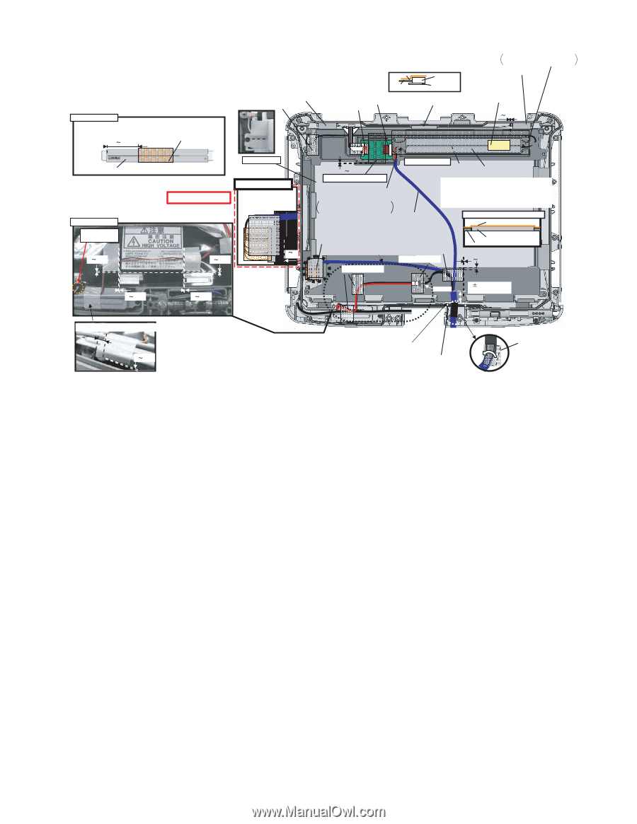
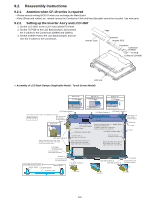
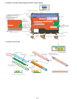
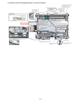
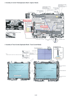
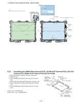
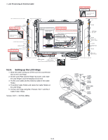
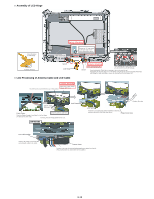
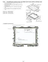
n Assembly of Inverter PCB (Applicable Model : Touch Screen Model) Inverter Ass'y Confirm the direction of the Inverter board when attaching. 30 35mm Inverter Mil Sheet Insert it between the ribs. (Fit to the Cabinet.) LCD Side Cushion E Insulation Parts Insulation Parts Avoid any stress on the Cable when connecting the CCFL Cable. Hold the Connector part when connecting/disconnecting. Attach it to the Connector and FPC. LCD Side Cushion E 12 Connector Insert it between the ribs. FPC PWB (Fit to the Cabinet.) Cushion High TS PWB LCD Side Cushion F Voltage Label Connect Insert it between the ribs. (Fit to the Cabinet.) 0 3mm Inverter Ass'y Details of Cable Avoid running over this rib. 0 1mm The gap side is front. Safety Working 0 1mm LCD Ass'y Details of "A" Ensure the edge of the conductive fabric is not frayed. 1 2 mm A Inverter Ass'y 0 0.5mm Sub material: Pet Tape 1 Connect the Cable to the Tape left and right Connectors. Attach the Inverter Ass'y in the Avoid any stress on the Cable when connecting it. Hold the Connector part when connecting/disconnecting. LCD Cable TS middle of right and left. Attach the surplus of the right and left sides on the Back Dumper as shown below and overlap on the CCFL Cable. Attach the Pet Sheet over the Core. Note for attaching Conductive Tape Conductive Tape Wind round the LCD Cable a few times and attach it. Sield Sheet Avoid getting under the Sheet. Fix the two Cables. Insulation Parts Inverter Ass'y LCD Back Dumper 0 4mm Insulation Parts 0 1mm 0 1mm Connect 6 2mm from the branch point Attach coming over the end of steel plate by 1 to 2 mm. 0 1mm Avoid any stress on the Tab part of the LCD Module because the line comes off. Wrap of Antenna Cable Cushion E Conductive Tape Wrap over the Antenna Cable Cushion and the Cable. 9-11
-
 1
1 -
2
-
3
-
4
-
5
-
6
-
7
-
8
-
9
-
10
-
11
-
12
-
13
-
14
-
15
-
16
-
17
-
18
-
19
-
20
-
21
-
22
-
23
-
24
-
25
-
26
-
 27
27 -
 28
28 -
 29
29 -
 30
30 -
 31
31 -
 32
32 -
 33
33 -
 34
34 -
 35
35 -
 36
36 -
 37
37 -
38
-
39
-
40
-
41
-
42
-
43
-
44
-
45
-
46
-
47
-
48
-
49
-
50
-
51
-
52
-
53
-
54
-
55
-
56
-
57
-
58
-
59
-
60
-
61
-
62
-
63
-
64
-
65
-
66
-
67
-
68
-
69
-
70
-
71
-
72
-
73
-
74
-
75
-
76
-
77
-
78
-
79
-
80
-
81
-
82
-
83
-
84
 |
 |