Panasonic CF-19CDBAXVM Service Manual - Page 53
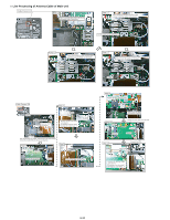
Line Processing of Antenna Cable of Main Unit
 |
UPC - 092281864785
View all Panasonic CF-19CDBAXVM manuals
Add to My Manuals
Save this manual to your list of manuals |
Page 53 highlights
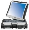
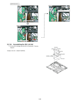
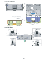
n Line Processing of Antenna Cable of Main Unit Cable Process 1/3 Step 1 Place brown/blue/gray cables at left and white/black cables downward. Step 3 After connecting the black antenna cable, connect it into the Holder as illustrated. Put the surplus under along the rib. Step 2 After connecting the white antenna cable, connect it into the Holder as illustrated. Step 4 After connecting the gray antenna cable, connect it into the Holder as illustrated. Cable Cable Process 2/3 Step 7 Step 5 Audio PCB Ass'y Insert the FPC, 0 2mm Lock Check Sheet Attach Side Remove the Release Paper and attach it. To prevent from the cable damage by screw head. 0 1mm 0 1mm Tape 2 5mm After processing the cables, inserting the FPC and locking, incline the Audio PCB into the arrow direction. Step 6 Screw Screw Step 8 Fix the Ausio PCB Screw Connect the gray antenna cable. Step 9 Connect the blue antenna cable. Step 10 Screw Screw Insert it into the right notch of the Clamper. Check the blue cable from the hole. Screw Screw Step 11 Connect the FPC Sheet Attach Side 0 1mm 0 1mm Remove the Release Paper and attach it. To prevent from the cable damage by screw bead. 9-32
-
 1
1 -
2
-
3
-
4
-
5
-
6
-
7
-
8
-
9
-
10
-
11
-
12
-
13
-
14
-
15
-
16
-
17
-
18
-
19
-
20
-
21
-
22
-
23
-
24
-
25
-
26
-
27
-
28
-
29
-
30
-
31
-
32
-
33
-
34
-
35
-
36
-
37
-
38
-
39
-
40
-
41
-
42
-
43
-
44
-
45
-
46
-
47
-
 48
48 -
 49
49 -
 50
50 -
 51
51 -
 52
52 -
 53
53 -
 54
54 -
 55
55 -
 56
56 -
 57
57 -
 58
58 -
59
-
60
-
61
-
62
-
63
-
64
-
65
-
66
-
67
-
68
-
69
-
70
-
71
-
72
-
73
-
74
-
75
-
76
-
77
-
78
-
79
-
80
-
81
-
82
-
83
-
84
 |
 |