Panasonic CF-19CDBAXVM Service Manual - Page 51
Setting the Audio PCB
 |
UPC - 092281864785
View all Panasonic CF-19CDBAXVM manuals
Add to My Manuals
Save this manual to your list of manuals |
Page 51 highlights
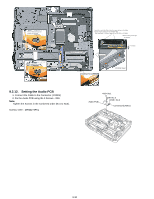
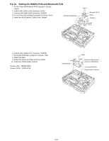
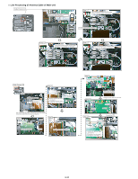
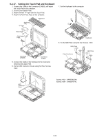
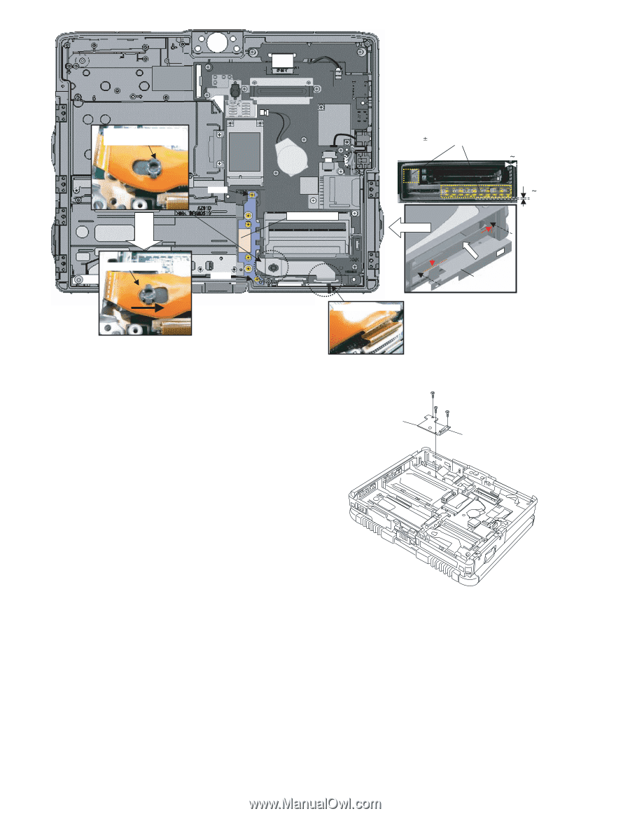
Ensure that both top and bottom are hooked. Screw Slide the Battery FPC Ass'y Screw Battery FPC Ass'y Insert the end of the Sheet into the space between the Main Board and the bottom of the PCMCIA Slot. (Left and Right 0.5mm, Apply 20 to 30N (2.0 to 3.0 Kgf)) Attach it fitting to the right. 0 0.5mm 0 0.5mm Side surface Insert the FPC as illustrated SD Blind Sheet 9.2.12. Setting the Audio PCB 1. Connect the Cable to the Connector. (CN901) 2. Fix the Audio PCB using the 3 Screws. Note: Tighten the Screws in the numbered order (No1 to No3). Screws : DRSB2+5FKL Audio PCB :No1 :No.2 :No.3 Connector(CN901) 9-30
-
 1
1 -
2
-
3
-
4
-
5
-
6
-
7
-
8
-
9
-
10
-
11
-
12
-
13
-
14
-
15
-
16
-
17
-
18
-
19
-
20
-
21
-
22
-
23
-
24
-
25
-
26
-
27
-
28
-
29
-
30
-
31
-
32
-
33
-
34
-
35
-
36
-
37
-
38
-
39
-
40
-
41
-
42
-
43
-
44
-
45
-
 46
46 -
 47
47 -
 48
48 -
 49
49 -
 50
50 -
 51
51 -
 52
52 -
 53
53 -
 54
54 -
 55
55 -
 56
56 -
57
-
58
-
59
-
60
-
61
-
62
-
63
-
64
-
65
-
66
-
67
-
68
-
69
-
70
-
71
-
72
-
73
-
74
-
75
-
76
-
77
-
78
-
79
-
80
-
81
-
82
-
83
-
84
 |
 |
9-30
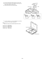
9.2.12.
Setting the Audio PCB
1. Connect the Cable to the Connector. (CN901)
2. Fix the Audio PCB using the 3 Screws. <N9>
Note:
Tighten the Screws in the numbered order (No1 to No3).
Screws <N9> : DRSB2+5FKL
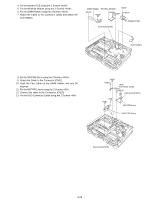
Screw
Screw
SD Blind Sheet
Battery FPC Ass’y
Ensure that both top and
bottom are hooked.
Slide the Battery FPC Ass’y
Insert the FPC as illustrated
Side surface
Insert the end of the Sheet into the space between the Main
Board and the bottom of the PCMCIA Slot.
(Left and Right
0.5mm, Apply 20 to 30N (2.0 to 3.0 Kgf))
Attach it fitting to the right.
0
0.5mm
0
0.5mm
<N9>:No1
<N9>:No.2
Audio PCB
Connector(CN901)
<N9>:No.3