Panasonic CF-19CDBAXVM Service Manual - Page 26
Removing the I/O PCB Ass'y, 1.11., Removing the Power SW PCB, 1.12., Removing the left LED
 |
UPC - 092281864785
View all Panasonic CF-19CDBAXVM manuals
Add to My Manuals
Save this manual to your list of manuals |
Page 26 highlights
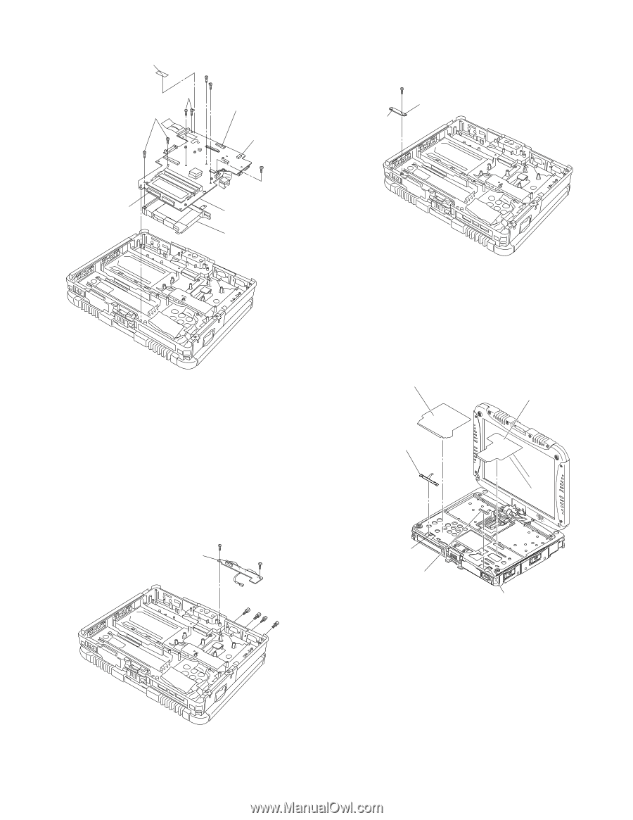
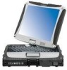
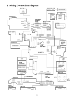
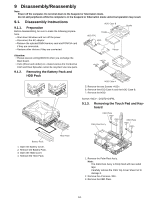
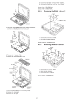
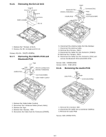
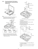
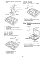
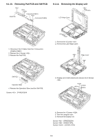
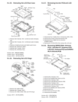
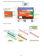
14. Remove the 2 Screws , and remove the DIMM Holder. Tape Connector(CN9) Connector(CN14) Screws : DFHE5058ZB Screws : DRSB2+5FKL 9.1.11. Removing the Power SW PCB Connector(CN9) Power SW PCB Connector(CN23) Main PCB Combo Socket 15. Remove the Tape. 16. Disconnect the 3 Cables from the 3 Connectors. (CN9,CN14,CN23) 17. Remove the 7 Screws , and remove the Main PCB and Combo Socket. Screws : DFHE5108ZA Screws : DRSB2+10FKL Screws : DRSB2+5FKL Screws : XSB2+3FNL 9.1.10. Removing the I/O PCB Ass'y I/O PCB Ass'y 1. Remove the Screw . 2. Disconnect the Cable from the Connector (CN9). 3. Remove the Power SW PCB. Screw : DFHE5025XA 9.1.12. Removing the left LED and right LED PCB Release Paper Release Paper left LED PCB Connector(CN806) right LED PCB Connector(CN801) 1. Remove the two Release Papers. 2. Disconnect the Cable from the Connector (CN806). 3. Remove the left LED PCB. 4. Disconnect the Cable from the Connector (CN801). 5. Remove the right LED PCB. 1. Remove the 4 D-SUB Screws . 2. Remove the 2 Screws . 3. Remove the I/O PCB Ass'y. 9-5
-
 1
1 -
2
-
3
-
4
-
5
-
6
-
7
-
8
-
9
-
10
-
11
-
12
-
13
-
14
-
15
-
16
-
17
-
18
-
19
-
20
-
 21
21 -
 22
22 -
 23
23 -
 24
24 -
 25
25 -
 26
26 -
 27
27 -
 28
28 -
 29
29 -
 30
30 -
 31
31 -
32
-
33
-
34
-
35
-
36
-
37
-
38
-
39
-
40
-
41
-
42
-
43
-
44
-
45
-
46
-
47
-
48
-
49
-
50
-
51
-
52
-
53
-
54
-
55
-
56
-
57
-
58
-
59
-
60
-
61
-
62
-
63
-
64
-
65
-
66
-
67
-
68
-
69
-
70
-
71
-
72
-
73
-
74
-
75
-
76
-
77
-
78
-
79
-
80
-
81
-
82
-
83
-
84
 |
 |