Panasonic CF-19CDBAXVM Service Manual - Page 36
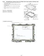
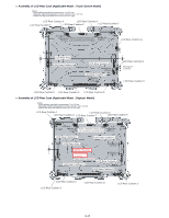
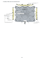
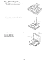
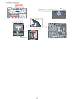
Assembly of LCD Hinge, Line Processing of Antenna Cable and LCD Cable
 |
UPC - 092281864785
View all Panasonic CF-19CDBAXVM manuals
Add to My Manuals
Save this manual to your list of manuals |
Page 36 highlights
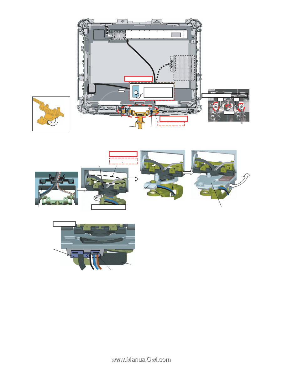
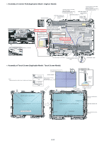
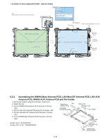
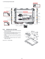
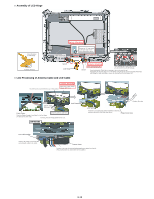
n Assembly of LCD Hinge Safety Working Initial Condition of LCD Hinge Cable Hold Plate Ensure the "C" side comes to the lower right corner when viewing from above. Cable Hold Plate Using the fixing jig when fixing the Hinge Fix Fix Rotation Direction Screw LCD Hinge n Line Processing of Antenna Cable and LCD Cable Tighten Safety Working Avoid catching the Cable. If you arrange the Cable in the area, you do not need to use the fixing jig. Screw Avoid catching the Cable (when repairing or when not using the jig). Temporarily fix the both sides ("A") of the Hinge using the Screw, and fix the Cable Hold Plate. After fixing the Cable Hold Plate, remove the screws from the both sides ("A"). Safety Working Allow some cable margin. You will hear the sound when they are firmly jointed. Margin: 22 3 mm Turn the Cable 360 degree. Lock Plate Assy Cable Holder Wind the Antenna cable first. Pass the Cables through it, and then fix it to the Hinge. (Fix directly the other side.) For fixing, hold the Hinge parallel to the LCD. LCD Rear side Rotation Direction Lock Spring Insert the Lock Spring (the bottom diameter is shorter), and then insert the Lock Plate from above. Hinge Cover Assy LCD Cable Holder Joint it to the Hinge Cover hook after connecting the cable to the notch. Protect Sheet Process in the order of black/white/blue/gray/brown cables from the left. (This process does not need if there are not cables.) 9-15
-
 1
1 -
2
-
3
-
4
-
5
-
6
-
7
-
8
-
9
-
10
-
11
-
12
-
13
-
14
-
15
-
16
-
17
-
18
-
19
-
20
-
21
-
22
-
23
-
24
-
25
-
26
-
27
-
28
-
29
-
30
-
 31
31 -
 32
32 -
 33
33 -
 34
34 -
 35
35 -
 36
36 -
 37
37 -
 38
38 -
 39
39 -
 40
40 -
 41
41 -
42
-
43
-
44
-
45
-
46
-
47
-
48
-
49
-
50
-
51
-
52
-
53
-
54
-
55
-
56
-
57
-
58
-
59
-
60
-
61
-
62
-
63
-
64
-
65
-
66
-
67
-
68
-
69
-
70
-
71
-
72
-
73
-
74
-
75
-
76
-
77
-
78
-
79
-
80
-
81
-
82
-
83
-
84
 |
 |