| Section |
Page |
| System Components |
2 |
| Attention |
3 |
| Important Safety Instructions |
5 |
| F.C.C. Requirements and Relevant Information |
7 |
| Introduction |
9 |
| Contents |
10 |
| System Outline |
17 |
| 1.1 System Highlights |
18 |
| 1.2 Basic System Construction |
19 |
| 1.3 Proprietary Telephones |
19 |
| 1.4 Pre-installed Cards |
20 |
| 1.4.1 Caller ID Card |
20 |
| 1.4.2 Doorphone/Door Opener Card |
20 |
| 1.5 Specifications |
21 |
| 1.5.1 General Description |
21 |
| 1.5.2 Characteristics |
22 |
| 1.5.3 System Capacity |
23 |
| Installation |
25 |
| 2.1 Before Installation |
26 |
| 2.2 Installation of the Main Unit |
28 |
| 2.2.1 Unpacking |
28 |
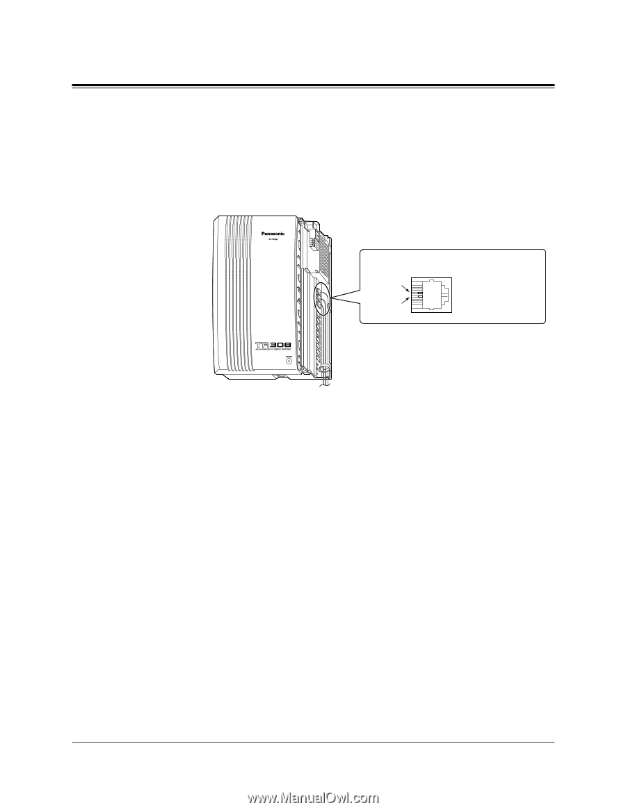
| 2.2.2 Location of Interfaces |
28 |
| 2.2.3 Wall Mounting |
29 |
| 2.2.4 Frame Ground Connection |
30 |
| 2.3 Connection |
32 |
| 2.3.1 System Connection Diagram |
32 |
| 2.3.2 Opening the Side Cover |
33 |
| 2.3.3 Outside (CO) Line Connection |
34 |
| 2.3.4 Extension Connection |
37 |
| 2.3.5 External Pager (Paging Equipment) Connection |
38 |
| 2.3.6 External Music Source Connection |
39 |
| 2.3.7 Paralleled Telephone Connection(for a Proprietary Telephone and a Single Line Telephone) |
40 |
| 2.3.8 Polarity Sensitive Telephone Connection |
41 |
| 2.3.9 Printer and PC Connection |
42 |
| 2.4 Doorphone/Door Opener Card |
45 |
| 2.4.1 Doorphone and Door Opener connection |
45 |
| 2.4.2 Doorbell/Door Chime Connection |
49 |
| 2.4.3 Securing the cords |
50 |
| 2.5 Auxiliary Connection for Power Failure Transfer |
51 |
| 2.6 Closing the Side Cover |
52 |
| 2.7 Starting the System for the First Time |
53 |
| 2.8 System Restart |
54 |
| 2.9 System Data Clear |
55 |
| Features |
57 |
| A |
58 |
| Absent Message Capability |
58 |
| Account Code Entry |
59 |
| Answering, Direct Outside (CO) Line |
60 |
| Automatic Callback Busy (Camp-On) |
61 |
| B |
62 |
| Background Music (BGM) |
62 |
| Busy Lamp Field |
63 |
| Busy Station Signaling (BSS) |
63 |
| Button, Direct Station Selection (DSS) |
64 |
| Button, Flexible |
65 |
| Button, Group-CO (G-CO) |
68 |
| Button, Other-CO (O-CO) |
69 |
| Button, Single-CO (S-CO) |
70 |
| Buttons on Proprietary Telephones |
71 |
| C |
74 |
| CALL FORWARDING FEATURES – SUMMARY |
74 |
| Call Forwarding – All Calls |
74 |
| Call Forwarding – Busy/No Answer |
75 |
| Call Forwarding – Follow Me |
76 |
| Call Forwarding – to an Outside (CO) Line |
77 |
| Call Hold – Intercom |
78 |
| Call Hold – Outside (CO) Line |
79 |
| Call Hold, Exclusive – Intercom |
80 |
| Call Hold, Exclusive – Outside (CO) Line |
80 |
| Call Hold Retrieve – Intercom |
81 |
| Call Hold Retrieve – Outside (CO) Line |
81 |
| Call Log, Incoming |
82 |
| Call Park |
84 |
| Call Pickup, Directed |
84 |
| Call Pickup, Group |
85 |
| Call Pickup Deny |
85 |
| Call Retrieving from a TAM (Telephone Answering Machine) |
86 |
| Call Splitting |
86 |
| CALL TRANSFER FEATURES – SUMMARY |
87 |
| Call Transfer, Screened – to Extension |
87 |
| Call Transfer, Screened – to an Outside (CO) Line |
88 |
| Call Transfer, Unscreened – to Extension |
89 |
| Call Waiting |
90 |
| Call Waiting from a Central Office |
91 |
| Caller ID |
92 |
| Caller ID Call Waiting |
93 |
| Calling Party Control (CPC) Signal Detection |
94 |
| Conference |
95 |
| Conference, Unattended |
96 |
| Confirmation Tones |
97 |
| D |
99 |
| Data Line Security |
99 |
| Dial Tones, Distinctive |
100 |
| Dial Type Selection |
101 |
| Direct In Lines (DIL) |
102 |
| Direct Inward System Access (DISA) |
103 |
| Display, Call Information |
109 |
| Display, in Idle |
110 |
| Display, Self-Extension Number |
111 |
| Display Contrast Adjustment |
111 |
| Do Not Disturb (DND) |
112 |
| Do Not Disturb (DND) Override |
112 |
| Door Opener |
113 |
| Doorbell/Door Chime |
114 |
| Doorphone Call |
116 |
| E |
117 |
| Electronic Station Lockout |
117 |
| Emergency Call |
118 |
| End-to-End DTMF Signaling (Tone Through) |
118 |
| Executive Busy Override – Extension |
119 |
| Executive Busy Override – Outside (CO) Line |
120 |
| Extension Group |
121 |
| External Feature Access |
122 |
| F |
123 |
| Flash |
123 |
| H |
123 |
| Handset/Headset |
123 |
| Hands-free Answerback |
124 |
| Hands-free Operation |
124 |
| Hold Alarm/Hold Recall |
125 |
| Host PBX Access |
126 |
| I |
127 |
| Intercept Routing |
127 |
| Intercom Calling |
128 |
| L |
129 |
| LED Indication, Intercom |
129 |
| LED Indication, Outside (CO) Line |
130 |
| Limited Call Duration |
131 |
| Line Access, Automatic |
132 |
| Line Access, Direct |
133 |
| Line Access, Individual |
134 |
| Line Access, Outside (CO) Line Group |
135 |
| Line Preference – Incoming (No Line/Prime Line/Ringing Line) |
136 |
| Line Preference – Outgoing (Idle Line/No Line/Prime Line) |
137 |
| Local Carrier-Based Voice Mail Service |
138 |
| Lockout |
139 |
| Log-In/Log-Out |
140 |
| M |
141 |
| Manager Extension |
141 |
| Message Waiting |
142 |
| Message Waiting for Another Extension |
143 |
| Microphone Mute |
144 |
| Mixed Station Capacities |
144 |
| Music on Hold |
145 |
| O |
146 |
| One-Touch Dialing |
146 |
| One-Touch Transfer Using a DSS Button |
147 |
| Operator |
148 |
| Operator Call |
148 |
| Outside (CO) Line Connection Assignment |
149 |
| Outside (CO) Line Connection Assignment – Outgoing |
149 |
| Outside (CO) Line Group |
150 |
| P |
151 |
| PAGING FEATURES – SUMMARY |
151 |
| Paging – All |
151 |
| Paging – External |
152 |
| Paging – Group |
152 |
| Paralleled Telephone |
153 |
| Pause Insertion, Automatic |
154 |
| Personal Speed Dialing |
155 |
| Pickup Dialing |
156 |
| Power Failure Transfer |
157 |
| Pulse to Tone Conversion |
158 |
| R |
159 |
| Redial, Last Number |
159 |
| Redial, Saved Number |
159 |
| Ring Group |
160 |
| Ringing, Delayed |
160 |
| Ringing, Discriminating |
161 |
| Ringing Pattern Selection for Intercom Calls and Outside (CO) Lines |
162 |
| Ringing Tone Selection for Doorphones |
163 |
| Room Monitor |
165 |
| S |
166 |
| Secret Dialing |
166 |
| Station Feature Clear |
167 |
| Station Hunting |
168 |
| Station Message Detail Recording (SMDR) |
169 |
| Station Programming |
171 |
| Station Programming Data Default Set |
172 |
| System Data Default Set |
173 |
| System Programming with a Proprietary Telephone |
173 |
| System Speed Dialing |
174 |
| T |
175 |
| Time (Day/Night/Lunch) Service |
175 |
| Time-Out, Variable |
176 |
| Timed Reminder |
178 |
| Timed Reminder, Remote (Wake-Up Call) |
178 |
| Toll Restriction |
179 |
| Toll Restriction for Special Carrier Access |
185 |
| Toll Restriction for System Speed Dialing |
186 |
| Toll Restriction Override by Account Codes |
187 |
| Toll Restriction — Station Lock Boundary Class |
189 |
| V |
190 |
| Volume Control – Handset Receiver/Headset/Ringer/Speaker |
190 |
| W |
191 |
| Walking COS |
191 |
| System Programming |
193 |
| 4.1 General Programming Instructions |
194 |
| 4.1.1 Using Proprietary Telephones |
195 |
| 4.1.2 Programming Methods |
197 |
| 4.1.3 Entering Characters |
198 |
| 4.1.4 Programming Example |
200 |
| 4.2 System Programming |
201 |
| [000]- |
201 |
| [000] Date and Time Setting |
201 |
| [001] System Speed Dialing Entry |
203 |
| [002] System Password |
205 |
| [005] One-Touch Transfer Using a DSS Button |
206 |
| [006] Time (Day/Night/Lunch) Service Changing Mode |
207 |
| [007] Time (Day/Night/Lunch) Service Start Time |
208 |
| [008] Operator Assignment |
210 |
| [009] Extension Number Assignment |
211 |
| [010] LCD Time Display Selection |
212 |
| [011] System Speed Dialing Name Setting |
213 |
| [100]- |
214 |
| [100] Hunting Group Set |
214 |
| [101] Station Hunting Type |
215 |
| [104] Hold Mode Selection |
216 |
| [105] Conference Tone |
217 |
| [106] External Paging Access Tone |
218 |
| [107] DTMF Receiver Check |
219 |
| [108] Flash Mode for a Station Locked Extension |
220 |
| [109] CO Indicator Assignment |
221 |
| [110] Flash Key Mode |
222 |
| [111] Hold Music Selection |
223 |
| [112] DSS Button Indication Mode |
224 |
| [115] Extension Ringing Pattern Selection |
225 |
| [117] Call Pickup Tone |
226 |
| [118] Pulse Restriction |
227 |
| [119] Redialing After Pulse to Tone Conversion |
228 |
| [125] Toll Restriction Check for * and # |
229 |
| [200]- |
230 |
| [200] Hold Recall Time |
230 |
| [201] Transfer Recall Time |
231 |
| [202] Call Forwarding Start Time |
232 |
| [203] Pickup Dial Delay Time |
233 |
| [204] Call Duration Count Start Time |
234 |
| [205] Outside-to-Outside (CO-to-CO) Line Duration Time Limit |
235 |
| [206] Dialing Start Time |
236 |
| [208] Interdigit Time |
237 |
| [211] No Dial Disconnection |
238 |
| [300]- |
239 |
| [300] Carrier Code Assignment |
239 |
| [301] Toll Restriction — System Speed Dialing Boundary Class |
240 |
| [302]-[305] Toll Restriction — Class 2 – 5 Denied Codes |
241 |
| [306] Toll Restriction — Exception Codes |
242 |
| [309] Emergency Dial Number Set |
243 |
| [310] Account Codes |
244 |
| [311] Automatic Pause Insertion Codes |
245 |
| [312] Toll Restriction — Station Lock Boundary Class |
246 |
| [400]- |
247 |
| [400] Outside (CO) Line Connection Assignment |
247 |
| [401] Dial Mode |
248 |
| [402] Pulse Speed Selection |
249 |
| [403] Host PBX Access Codes |
250 |
| [404] Outside (CO) Line Group Assignment |
252 |
| [405]-[407] Flexible Outward Dialing Assignment — Day/Night/Lunch |
253 |
| [408]-[410] Flexible Ringing Assignment — Day/Night/Lunch |
254 |
| [411]-[413] Delayed Ringing Assignment — Day/Night/Lunch |
256 |
| [414]-[416] Outside (CO) Line Mode — Day/Night/Lunch |
258 |
| [417] Pause Time |
260 |
| [418] Flash Time |
261 |
| [419] Automatic Designated Outside (CO) Line Access |
262 |
| [420] Calling Party Control (CPC) Signal |
263 |
| [421] CPC Detection for Outgoing Calls |
265 |
| [422] Disconnect Time |
266 |
| [423] Outside (CO) Line Ringing Pattern Selection |
267 |
| [435] Local Carrier-Based Voice Mail Signaling Assignment |
268 |
| [436] Local Carrier-Based Voice Mail Access Dial Assignment |
269 |
| [437] Extension Access to Local Carrier-Based Voice Mail Assignment |
271 |
| [500]- |
272 |
| [500] DISA Incoming Dialing Mode Selection |
272 |
| [501] DISA Built-in Auto Attendant |
273 |
| [504] DISA Delayed Answer Time |
274 |
| [506] DISA Busy Mode |
275 |
| [507] DISA Intercept Mode |
276 |
| [508] DISA Ringing Time before Intercept |
277 |
| [509] DISA Ringing Time after Intercept |
278 |
| [510] DISA No Dial Mode |
279 |
| [511] DISA Security Type |
280 |
| [512] DISA Security Codes |
281 |
| [515] Intercept Time for Internal DISA |
282 |
| [516] DISA Incoming Assignment |
283 |
| [517] DISA AA Wait Time |
284 |
| [518] DISA Tone Selection after the Security Code |
285 |
| [530] DISA Security Codes Digits Selection |
286 |
| [600]- |
287 |
| [600] Extension Group Assignment |
287 |
| [601]-[603] TRS – Class of Service (COS) Assignment — Day/Night/Lunch |
288 |
| [604] Extension Name Setting |
289 |
| [605] Account Code Entry Mode |
290 |
| [606] Call Transfer to an Outside (CO) Line |
292 |
| [607] Call Forwarding to an Outside (CO) Line |
293 |
| [608] Executive Busy Override |
294 |
| [609] Do Not Disturb Override |
295 |
| [610] Paralleled Telephone Connection |
296 |
| [611] TAM (Telephone Answering Machine) Extension |
297 |
| [612] Room Monitor Assignment |
298 |
| [617] Wireless PT Port Assignment |
299 |
| [618] Message Waiting for Another Extension |
300 |
| [700]- |
301 |
| [700]-[702] Doorphone Ringing Assignment — Day/Night/Lunch |
301 |
| [703]-[705] Door Opener Assignment — Day/Night/Lunch |
302 |
| [706] Doorphone Ringing/Tone Pattern Selection |
303 |
| [707] Doorphone Access Tone Selection |
304 |
| [708] Doorphone Ringing Time |
305 |
| [709] Door Opener Time |
306 |
| [710] Doorphone Ring/Chime Selection |
307 |
| [711] Doorphone Chime Assignment |
308 |
| [712] Doorphone Chime Pattern Selection |
309 |
| [800]- |
311 |
| [800] SMDR RS-232C Communication Parameters |
311 |
| [801] SMDR Parameter |
313 |
| [802] Incoming/Outgoing Call Selection for Printing |
314 |
| [803] Secret Speed Dialing/One-Touch Dialing Printing |
315 |
| [804] System Data Dump |
316 |
| [805] SMDR Account Code Selection |
318 |
| [900]- |
319 |
| [900] Caller ID Assignment |
319 |
| [901] Caller ID Area Code Assignment |
320 |
| [902] Caller ID Modification for Local Calls |
321 |
| [903] Caller ID Modification for Long Distance Calls |
322 |
| [904] Caller ID Log Priority Selection |
323 |
| [906] Caller ID SMDR Format |
324 |
| [907] Caller ID SMDR Printout Selection |
325 |
| [908] Caller ID Call Waiting Time |
326 |
| [909] Common Area Call Log Check Assignment |
327 |
| [913] Caller ID Call Waiting Assignment |
328 |
| [914] Caller ID Call Waiting CAS Receive Time |
329 |
| [915] Caller ID Checksum |
330 |
| [963] Call Forwarding Selection |
331 |
| [968] Incoming Lamp Control |
332 |
| [998] ROM Version |
333 |
| [999] System Data Clear |
334 |
| List |
335 |
| 5.1 Tone/Ring Tone |
336 |
| 5.2 Default Values |
338 |
| Troubleshooting |
343 |
| 6.1 Installation |
344 |
| 6.2 Connection |
345 |
| 6.3 Operation |
346 |
 1
1 29
29 30
30 31
31 32
32 33
33 34
34 35
35 36
36 37
37 38
38 39
39