Panasonic KXTA30820 Installation Manual - Page 44
Serial Interface RS-232C Signals, Programming References, Feature Reference
 |
UPC - 037988850709
View all Panasonic KXTA30820 manuals
Add to My Manuals
Save this manual to your list of manuals |
Page 44 highlights
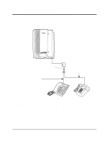
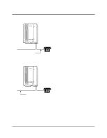
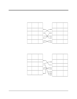
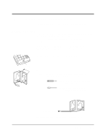
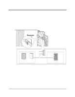
2.3.9 Printer and PC Connection Serial Interface (RS-232C) Signals Frame Ground: FG Connects the unit frame and the earth ground conductor of the AC power cord. Transmitted Data: SD (TXD) ....... (output) Conveys signals from the unit to the printer. A "Mark" condition is held unless data or BREAK signals are being transmitted. Received Data: RD (RXD) ........ Conveys signals from the printer. (input) Request to Send: RS (RTS) ........ (output) This lead remains ON whenever DR (DSR) is ON. Clear To Send: CS (CTS) ......... (input) When the CS (CTS) circuit is ON, it indicates that the printer is ready to receive data from the unit. The unit does not attempt to transfer data or receive data when the CS (CTS) circuit is OFF. Data Set Ready: DR (DSR) ........ (input) When the DR (DSR) circuit is ON, it indicates the printer is ready. The DR (DSR) circuit being ON does not indicate that communication has been established with the printer. Signal Ground: SG Connects the DC ground of the unit for all interface signals. Data Terminal Ready: ER (DTR) ...... (output) This signal line is turned ON by the unit to indicate that it is ON LINE. The ER (DTR) circuit being ON does not indicate that communication has been established with the printer. It is switched OFF when the unit is OFF LINE. Data Carrier Detect: CD (DCD) ...... (input) When ON, it indicates the data terminal (DTE) that the carrier signal is being received. Programming References Section 4, System Programming [800] SMDR RS-232C Communication Parameters [801] SMDR Parameter Feature Reference Section 3, Features Station Message Detail Recording (SMDR) 2-20 Installation
-
 1
1 -
2
-
3
-
4
-
5
-
6
-
7
-
8
-
9
-
10
-
11
-
12
-
13
-
14
-
15
-
16
-
17
-
18
-
19
-
20
-
21
-
22
-
23
-
24
-
25
-
26
-
27
-
28
-
29
-
30
-
31
-
32
-
33
-
34
-
35
-
36
-
37
-
38
-
 39
39 -
 40
40 -
 41
41 -
 42
42 -
 43
43 -
 44
44 -
 45
45 -
 46
46 -
 47
47 -
 48
48 -
 49
49 -
50
-
51
-
52
-
53
-
54
-
55
-
56
-
57
-
58
-
59
-
60
-
61
-
62
-
63
-
64
-
65
-
66
-
67
-
68
-
69
-
70
-
71
-
72
-
73
-
74
-
75
-
76
-
77
-
78
-
79
-
80
-
81
-
82
-
83
-
84
-
85
-
86
-
87
-
88
-
89
-
90
-
91
-
92
-
93
-
94
-
95
-
96
-
97
-
98
-
99
-
100
-
101
-
102
-
103
-
104
-
105
-
106
-
107
-
108
-
109
-
110
-
111
-
112
-
113
-
114
-
115
-
116
-
117
-
118
-
119
-
120
-
121
-
122
-
123
-
124
-
125
-
126
-
127
-
128
-
129
-
130
-
131
-
132
-
133
-
134
-
135
-
136
-
137
-
138
-
139
-
140
-
141
-
142
-
143
-
144
-
145
-
146
-
147
-
148
-
149
-
150
-
151
-
152
-
153
-
154
-
155
-
156
-
157
-
158
-
159
-
160
-
161
-
162
-
163
-
164
-
165
-
166
-
167
-
168
-
169
-
170
-
171
-
172
-
173
-
174
-
175
-
176
-
177
-
178
-
179
-
180
-
181
-
182
-
183
-
184
-
185
-
186
-
187
-
188
-
189
-
190
-
191
-
192
-
193
-
194
-
195
-
196
-
197
-
198
-
199
-
200
-
201
-
202
-
203
-
204
-
205
-
206
-
207
-
208
-
209
-
210
-
211
-
212
-
213
-
214
-
215
-
216
-
217
-
218
-
219
-
220
-
221
-
222
-
223
-
224
-
225
-
226
-
227
-
228
-
229
-
230
-
231
-
232
-
233
-
234
-
235
-
236
-
237
-
238
-
239
-
240
-
241
-
242
-
243
-
244
-
245
-
246
-
247
-
248
-
249
-
250
-
251
-
252
-
253
-
254
-
255
-
256
-
257
-
258
-
259
-
260
-
261
-
262
-
263
-
264
-
265
-
266
-
267
-
268
-
269
-
270
-
271
-
272
-
273
-
274
-
275
-
276
-
277
-
278
-
279
-
280
-
281
-
282
-
283
-
284
-
285
-
286
-
287
-
288
-
289
-
290
-
291
-
292
-
293
-
294
-
295
-
296
-
297
-
298
-
299
-
300
-
301
-
302
-
303
-
304
-
305
-
306
-
307
-
308
-
309
-
310
-
311
-
312
-
313
-
314
-
315
-
316
-
317
-
318
-
319
-
320
-
321
-
322
-
323
-
324
-
325
-
326
-
327
-
328
-
329
-
330
-
331
-
332
-
333
-
334
-
335
-
336
-
337
-
338
-
339
-
340
-
341
-
342
-
343
-
344
-
345
-
346
-
347
-
348
-
349
-
350
-
351
-
352
-
353
-
354
-
355
-
356
-
357
-
358
-
359
-
360
-
361
-
362
-
363
-
364
-
365
-
366
-
367
-
368
-
369
-
370
-
371
-
372
-
373
-
374
 |
 |