Panasonic SDC615 AJSDC615 User Guide
Panasonic SDC615 - AJ Camcorder - 520 KP Manual
 |
UPC - 791871302699
View all Panasonic SDC615 manuals
Add to My Manuals
Save this manual to your list of manuals |
Panasonic SDC615 manual content summary:
- Panasonic SDC615 | AJSDC615 User Guide - Page 1
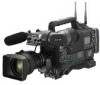
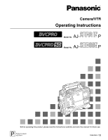
Camera/VTR Operating Instructions AJ- Model No. P AJ- Model No. P Before operating this product, please read the instructions carefully and save this manual for future use. P Printed in Japan VQT0N11 F0904W0 -F @ - Panasonic SDC615 | AJSDC615 User Guide - Page 2
USER SERVICEABLE PARTS INSIDE. REFER TO SERVICING TO QUALIFIED SERVICE with the instruction manual, may instructions apply to both the AJ-SDC615 and AJ-SDC905. However, descriptions which apply solely to the AJ-SDC615 are indicated by SDC615 ; similarly, descriptions which apply solely to the AJ - Panasonic SDC615 | AJSDC615 User Guide - Page 3
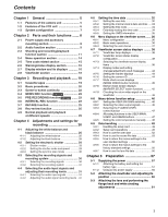
REC function SDC615 22 3-5 PRE-RECORDING function SDC905 ........ 23 3-6 INTERVAL REC function 23 3-7 RETAKE function 25 3-8 Rec-review function 4-8-4 Allocating functions to the USER MAIN, USER1 and USER2 buttons 47 4-8-5 Setting the color temperature manually ....... 48 4-9 Data handling - Panasonic SDC615 | AJSDC615 User Guide - Page 4
Attaching the rain cover 69 5-9 Connecting the extension control unit (AJ-EC3P 69 5-10 Attacching the FEONT AUDIO LEVEL control knob CAMERA SETTING 89 7-4 VF 89 7-4-1 VF DISPLAYS 89 7-4-2 VF MARKER 90 7-4-3 USER BOX 90 7-4-4 VF INDICATOR1 90 7-4-5 VF INDICATOR2 91 7-4-6 MODE CHECK IND 91 - Panasonic SDC615 | AJSDC615 User Guide - Page 5
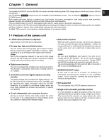
AJ-SDC615 and AJ-SDC905 are camera recorders featuring three CCD image sensors which each have a 2/3-inch on-chip lens. The AJ-SDC905 SDC905 supports both the DVCPRO and DVCPRO50 formats. (The AJ-SDC615 SDC615 supports only the DVCPRO used on its own, one set of user data and four sets of scene file - Panasonic SDC615 | AJSDC615 User Guide - Page 6
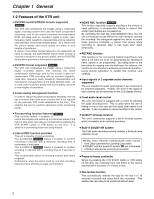
DVCPRO format when economy is to be given precedence. ≥ DVCPRO format supported SDC615 one frame. The AJ-SDC615 SDC615 makes it possible to recording level. This is useful when the user is filming on his or her own of +1 frame or less. ≥ Rec-review function This automatically rewinds the tape for the - Panasonic SDC615 | AJSDC615 User Guide - Page 7
and played back. ≥ Metadata supported The unit allows information from the AJ-GPS900G GPS unit to be AJ-HT901 Video camera-recorder: AJ-SDC615 AJ-SDC905 AC adapter: AJ-B75 SD memory cards Multimedia cards Cleaning tape: AJ-CL12MP Cassette tapes: AJ-5P23MP AJ-5P33MP AJ-P12MP AJ-P24MP AJ-P33MP AJ - Panasonic SDC615 | AJSDC615 User Guide - Page 8
AJ-B75 AC adapter (optional accessory). 4 BREAKER switch If an excessively high current flows inside the unit due to some problem service person. If there are no problems, the power will come back on. 5 GPS connector The connector from AJ , refer to the operating instructions of the lenses concerned. - Panasonic SDC615 | AJSDC615 User Guide - Page 9
: Set here for automatic adjustment. MAN : Set here for manual adjustment. 4 AUDIO IN (audio input selector) switch These are of audio channels 1 and 2 are output to the remote control unit (AJ-RC905). The signals are output now as is without the adjustment of DVCPRO format (25 Mbps) is set. 9 - Panasonic SDC615 | AJSDC615 User Guide - Page 10
2 or audio channels 3 and 4 are output from this connector. With the AJ-SDC905 SDC905 , the signals to be output can be selected using the MONITOR in the display window and viewfinder change when this switch is operated. SDC615 MONITOR SELECT (stereo/mix) STOMIX selector switch This is used to - Panasonic SDC615 | AJSDC615 User Guide - Page 11
Chapter 2 Parts and their functions 1 49 8 D EJECT GH 6 /REW STOP ª E 5 FF/ PLAY/PAUSE 1/; F 2 : 3 ; 2 = ? @ C AB I 2-3 Shooting and recording/playback function section Shooting and recording (camera unit) 1 FILTER (filter switching) controls These are used to select the filter - Panasonic SDC615 | AJSDC615 User Guide - Page 12
(ATW) performed with the automatic tracking system to memory B or allocate the color temperatures of the user's choice to memory A and memory B. For details, refer to "4-8-5 Setting the color temperature manually." 8 MODE CHECK button Each time this button is pressed, one of the four screen pages - Panasonic SDC615 | AJSDC615 User Guide - Page 13
is stopped. O When the signals input to the GENLOCK IN connector or DVCPRO connector are selected as the signals to be recorded, the switch setting will are output from here. @ ECU REMOTE (remote control) connector The AJ-EC3P extension control unit (optional accessory) is connected here. A MON OUT - Panasonic SDC615 | AJSDC615 User Guide - Page 14
and lamp When this button is pressed during stop, the tape is reviewed at high speed. Its lamp lights at this time. When it is pressed during playback or pause , the tape is reviewed at approximately 4 times the normal tape speed. Both the PLAY lamp and REW - Panasonic SDC615 | AJSDC615 User Guide - Page 15
digit which was made to flash by the SHIFT button 8 when the time code or user bits are to be set. 2 TC IN connector (BNC) Supply the time code which SHIFT button This causes the digit to be set to flash when the time code or user bits are to be set. 3 TC OUT connector (BNC) To lock the time code - Panasonic SDC615 | AJSDC615 User Guide - Page 16
6. ON : The back tally lamp and rear tally lamp operate. OFF : The back tally lamp and rear tally lamp do not operate. 3 WARNING lamp When a problem of some form or other occurs within the VTR unit, this lamp flashes or lights. 4 LIGHT switch This controls the lighting of the display window - Panasonic SDC615 | AJSDC615 User Guide - Page 17
DISPLAY switch and the real-time values of the hour and minutes in the time zone are displayed. Time counter display: The time code, CTL, user bits and real time are displayed. When UB has been selected by the DISPLAY switch, each time the HOLD button is pressed, the setting - Panasonic SDC615 | AJSDC615 User Guide - Page 18
tally lamp is hidden. 9 Eyepiece : Diopter adjustment ring This is adjusted in line with the camera operator's diopter in such a way that the user can see the image on the viewfinder screen most clearly. ; Connecting plug < Locking ring = Microphone holder > Viewfinder stopper This is used to attach - Panasonic SDC615 | AJSDC615 User Guide - Page 19
Chapter 3 Recording and playback 3-1 Cassette tapes Loading a cassette tape 1 Set the POWER switch to ON. When condensation has formed inside the unit, the HUMID display lights. Wait until this display is cleared before proceeding with the intended operation. HUMID display Checking for tape - Panasonic SDC615 | AJSDC615 User Guide - Page 20
Chapter 3 Recording and playback 3-2 Basic procedures This section describes the basic steps for shooting and recording. Before actually departing to shoot scenes, carry out inspections to ensure that the system is functioning properly. * For details on how to perform these inspections, refer to - Panasonic SDC615 | AJSDC615 User Guide - Page 21
Chapter 3 Recording and playback Procedure for shooting From adjusting the white balance and black balance to stopping the recording From adjusting the white balance and black balance to stopping the recording 1 Select the filter to match the lighting conditions. 3 2-1 If the white balance has - Panasonic SDC615 | AJSDC615 User Guide - Page 22
on a tape which has been recorded only in part. 3-4 NEWS REC function SDC615 The NEWS REC function is set using the NEWS REC MODE item after opening operation acknowledgment time, the unit can continuously record without the user having to interrupt the recording: this safeguards against the failure - Panasonic SDC615 | AJSDC615 User Guide - Page 23
its set time has been changed, and immediately after playback or rec-review has been performed. Immediately after any of these operations, therefore, the recording time in increments of one frame to be conducted. The AJ-SDC615 SDC615 enables recording in intervals with 3 a recording time of 2 - Panasonic SDC615 | AJSDC615 User Guide - Page 24
is in pause mode Selecting REC as the setting for one of either USER MAIN or USER1/USER2 buttons in advance enables quick start recording during pause prior to the moment when the tape stopped may not be recorded. ≥ With the AJ-SDC905 SDC905 , if a PLAY, FF or REW operation is performed after one- - Panasonic SDC615 | AJSDC615 User Guide - Page 25
back. The RET button function can be allocated by opening the screen from the OPERATION page and selecting settings for the USER MAIN SW, USER1 SW and USER2 SW items by performing menu operations. ≥The rec-review function cannot be used unless recording lasts for one or more seconds - Panasonic SDC615 | AJSDC615 User Guide - Page 26
Chapter 4 Adjustments and settings for recording In order to achieve images with a consistently high picture quality with this unit, it is necessary to adjust the black balance and white balance as the individual conditions demand. To achieve a higher picture quality, it is recommended that the - Panasonic SDC615 | AJSDC615 User Guide - Page 27
the unit must be inspected. For details, contact your nearest service center or your dealer. Messages relating to white balance adjustment can also be allocated to the USER MAIN, 4 USER1 or USER2 button. For details, refer to "4-8-4 Allocating functions to the USER MAIN, USER1 and USER2 buttons." - Panasonic SDC615 | AJSDC615 User Guide - Page 28
which has fluctuated significantly ≥When the value selected for the gain switch has been changed ≥ When the super gain setting has been performed using the USER MAIN, USER1 or USER2 button ≥ When the gamma ON/OFF setting has been changed 1 Set the switches as shown in the figure. ≥ Check - Panasonic SDC615 | AJSDC615 User Guide - Page 29
Chapter 4 Adjustments and settings for recording 4-2 Setting the electronic shutter This section describes the unit's electronic shutter, its settings and operations. 4-2-1 Shutter modes The table below lists the shutter modes in which the unit's #< SHUTTER SELECT > SUPER V MODE POSITION1 SEL - Panasonic SDC615 | AJSDC615 User Guide - Page 30
50 SET UP 25 PB MODE REC TALLY :CAM :16:9/50M :7.5%A :7.5%A :AUTO :RED SDC615 #< SYSTEM MODE > REC SIGNAL ASPECT SET UP PB MODE REC TALLY :CAM :16:9 operations, the user bits which are supplied to the DVCPRO connector are recorded. O The user bits which are supplied to the DVCPRO connector are - Panasonic SDC615 | AJSDC615 User Guide - Page 31
16:9 SDC615 : Signals are recorded in the DVCPRO format (25 Mbps) with an aspect ratio of 16:9. 4:3/25M SDC905 , 4:3 SDC615 : Signals are recorded in the DVCPRO format hand, when it is set to MAN, the levels can be adjusted manually. SDC905 O The same signals as for CH1 are recorded on audio track - Panasonic SDC615 | AJSDC615 User Guide - Page 32
range extends from 00:00:00:00 to 23:59:59:29. 4-5-1 Setting the user bits Memos and other information with up to 8 digits (dates, times) in hexadecimal not possible to record the contents that were set. The time code/user bits are also recorded in the VIDEO AUX area of the unit's memory. The - Panasonic SDC615 | AJSDC615 User Guide - Page 33
power OFF status. If a more accurate time reading is required, check the time and set it again when the power is turned on. When the AJ-GPS900G GPS unit is installed and the time can be received, the internal clock's time (local date/time) is kept accurate on the basis of - Panasonic SDC615 | AJSDC615 User Guide - Page 34
Chapter 4 Adjustments and settings for recording 4-5-3 Setting the time code 1 Set the DISPLAY switch to TC. Example 2: When connecting a multiple number of units and using one of them as the reference unit 2 Set the TCG switch to SET. 3 Open the screen from the VTR MENU page by - Panasonic SDC615 | AJSDC615 User Guide - Page 35
SETTING page by performing menu operations and INT is selected as the GENLOCK menu item setting. 4-5-5 Setting the UMID information This unit supports metadata UMIDs. As the UMID data, the user must first set the name of his or her country (with 3 or fewer characters), the name of the company or - Panasonic SDC615 | AJSDC615 User Guide - Page 36
held down. For details, contact your nearest service center or your dealer. Menu items are PAINT VF OPERATION FILE MAINTENANCE VTR MENU USER MENU SELECT PAINT: This item is used to monitor the camera's output waveforms. Video engineer support is normally required for this. The items under this - Panasonic SDC615 | AJSDC615 User Guide - Page 37
set, and the sub menu screen appears when the JOG dial button is pressed. **** MAIN MENU **** SYSTEM SETTING PAINT VF # OPERATION FILE MAINTENANCE VTR MENU USER MENU SELECT 3 Turn the JOG dial button to move the arrow (cursor) to the item which is to be set, and the setting item menu - Panasonic SDC615 | AJSDC615 User Guide - Page 38
AJ-VF20WB. (For details concerning viewfinder, refer to the operating instructions of each viewfinder.) 1 TALLY/REC (recording) lamp This lights up (red) during recording. It flashes when a problem .6V 1 EX2 4.0K: /34min PRO14 A -- GAIN -- -- USER SW GAIN -- LOW : 0 S.GAIN:30/36/42/48 2 MID - Panasonic SDC615 | AJSDC615 User Guide - Page 39
extender is in use. 2 MODE CHECK dedicated display area (STATUS: master gain, user switch gain) LOW/MID/HIGH -3 to 30 S.GAIN30/36/42/48 DS.GAIN6:/ that AWB cannot be executed during an ATW operation. This warns the user to recheck the position of the filter selector control during the AWB operation - Panasonic SDC615 | AJSDC615 User Guide - Page 40
SHADING operation has been not completed satisfactorily. This warns the user that the brightness is too high during the BLACK SHADING operation appears when the gain has been selected using the GAIN selector switch or USER button. This indicates the shutter speed value when the shutter speed has - Panasonic SDC615 | AJSDC615 User Guide - Page 41
during MODE CHECK button operations while the USER button functions as the RET switch. This problem has occurred during recording. This indicates that a problem has occurred in a mechanism. Depending on the nature of the trouble the signals supplied to the DVCPRO connector. This signals that it - Panasonic SDC615 | AJSDC615 User Guide - Page 42
Chapter 4 Adjustments and settings for recording Display item What is displayed Status when display appears > Zoom display Z00 to Z99 This indicates the amount of zoom. Note that this item is not displayed even if the display setting is ON if the lens is not equipped with a zoom position - Panasonic SDC615 | AJSDC615 User Guide - Page 43
Viewfinder screen display selection 1 Extender 2 MODE CHECK dedicated display area 3 Camera warning, message display area 4 Information allocated to USER buttons 5 Filter positions 6 WHITE BAL switch position 7 Cumulative gain display 8 Gain value 9 VTR warnings, information : AUDIO input system - Panasonic SDC615 | AJSDC615 User Guide - Page 44
for the changes made in the settings and for the messages advising the user of the adjustment results: for instance, the items displayed can be ) ABB OK When the extender has been selected Example) EXTENDER ON When a user button has been selected Example) UM: S.GAIN 30 dB When a marker select - Panasonic SDC615 | AJSDC615 User Guide - Page 45
Chapter 4 Adjustments and settings for recording 3 When the JOG dial button is pressed, the arrow (cursor) moves to the ID input area, and the input mode is established. 4 Press the JOG dial button again and turn it until the character to be set is displayed. When the button is turned, the - Panasonic SDC615 | AJSDC615 User Guide - Page 46
this unit. To select these functions, perform menu operations to open the screen from the OPERATION page and select the gain settings to moving subjects. Use a gain increase of up to +12 dB : with moving subjects. #< USER SW GAIN > S.GAIN ¢30dB ¢36dB ¢42dB ¢48dB DS.GAIN ¢ 6dB f (1/30) - Panasonic SDC615 | AJSDC615 User Guide - Page 47
buttons. To select this function, perform menu operations to open the screen from the OPERATION page, and set the desired function each with the USER MAIN SW item, USER1 SW item and USER2 SW item. 4 < USER SW > # USER MAIN SW USER1 SW USER2 SW :S.GAIN :D.ZOOM :DS.GAIN Setting items - Panasonic SDC615 | AJSDC615 User Guide - Page 48
to open the screen from the OPERATION page, and select VAR as the setting for the AWB A item and AWB B item. The manual color temperature adjustment function is now valid. The color temperatures are set using the COLOR TEMP PRE item, COLOR TEMP A item and COLOR TEMP B item - Panasonic SDC615 | AJSDC615 User Guide - Page 49
Chapter 4 Adjustments and settings for recording 4-9-2 Setup card operations To format the setup card, save the setting data on the card or read the saved data from the card, first perform a menu operation to open the screen from the FILE page. #< CARD READ/WRITE > R.SELECT - Panasonic SDC615 | AJSDC615 User Guide - Page 50
Chapter 4 Adjustments and settings for recording Giving a title to the selected file 4 Turn the JOG dial button to move the arrow (cursor) to the "TITLE : " item. < CARD READ/WRITE > R.SELECT READ W.SELECT WRITE CARD CONFIG TITLE READ :1 :1 # TITLE: 1: ******** 2: ******** 3: ******** 4: - Panasonic SDC615 | AJSDC615 User Guide - Page 51
Chapter 4 Adjustments and settings for recording 13 Turn the JOG dial button to move the arrow (cursor) to YES, and press the JOG dial button. When the data saving is completed, the following message appears. WRITE OK Loading the data of the selected file 4 Turn the JOG dial button to move the - Panasonic SDC615 | AJSDC615 User Guide - Page 52
open the screen from the FILE page, and to read the user data that has been written, first perform a menu operation to open the screen from the FILE page. #< INITIALIZE > READ FACTORY DATA WRITE USER DATA RESET LENS FILES 3 When the JOG dial button is pressed, the following - Panasonic SDC615 | AJSDC615 User Guide - Page 53
: ******** TITLE4 : ******** 4 Turn the JOG dial button to move the arrow (cursor) to YES, and press the JOG dial button. The data written in the user area of the unit's internal memory is now read, and the setting is completed. 5 Press the MENU button to exit the menu operations. 6 When the - Panasonic SDC615 | AJSDC615 User Guide - Page 54
number starts flashing. Turn the JOG dial button to select the scene file whose data is to be reset. < SCENE > READ USER DATA # SCENE SEL READ WRITE RESET :1 TITLE1 : ******** TITLE2 : ******** TITLE3 : ******** TITLE4 : ******** 4 Press the JOG dial button to enter the scene file. 5 Turn - Panasonic SDC615 | AJSDC615 User Guide - Page 55
JOG dial button is pressed, the arrow (cursor) moves to the title input area, and the input mode is established. < SCENE > READ USER DATA SCENE SEL :1 READ WRITE RESET ; TITLE1 : ******** TITLE2 : ******** TITLE3 : ******** TITLE4 : ******** 11 Turn the JOG dial button to move the arrow - Panasonic SDC615 | AJSDC615 User Guide - Page 56
standard settings. To do this, first perform a menu operation to open the screen from the FILE page. < INITIALIZE > # READ FACTORY DATA WRITE USER DATA RESET LENS FILES 1 Set the POWER switch to the OFF position. 2 Set the WHITE BAL switch to the PRST position. WHITE BAL switch 3 Set - Panasonic SDC615 | AJSDC615 User Guide - Page 57
this unit's power supply. To use the battery pack, there is the following choice of makes of batteries: ≥Panasonic ≥Anton-Bauer ≥IDX ≥PACO ≥Sony ≥ Batteries of other makes can also be supported by changing the setting menu but no guarantees are made for the system when they are actually used - Panasonic SDC615 | AJSDC615 User Guide - Page 58
Chapter 5 Preparation Using the BP-90 type battery pack 1 Remove the battery holder. 3 Connect the plug of the battery pack to the connector inside the battery case, and insert the battery pack into the case. Battery holder 2 Attach the battery case to the unit. 1 Connect the unit's cable with the - Panasonic SDC615 | AJSDC615 User Guide - Page 59
Chapter 5 Preparation Using the NP-1 type battery pack 1 Remove the battery holder. 2 Attach the NP-1 type battery case to the unit. 1 Tighten the mounting screws. 2 Tighten the power contact screws. 3 Insert the top of the detached cover in the direction shown by the arrows. 4 Align the holes in - Panasonic SDC615 | AJSDC615 User Guide - Page 60
5-1-2 Using an AC power supply When the AJ-B75 AC adapter made by Panasonic is used 1 Connect the DC OUT connector on the AJ-B75 AC adapter to the DC IN socket on the unit. 5-2 Attaching the viewfinder and adjusting its position Refer to the instructions accompanying the viewfinder. A slide rail is - Panasonic SDC615 | AJSDC615 User Guide - Page 61
. LENS socket 5 Proceed with the flange back adjustment for the lens. 5 ≥For details on how to handle the lens, refer to the operating instructions of the lens. ≥While the lens is removed, attach the mount cap to protect the unit. Mark 3 Push down the lever for securing the lens - Panasonic SDC615 | AJSDC615 User Guide - Page 62
and lens positions, refer also to the operating instructions that accompany the lens. 1 Attach the lens lens cable. 2 Set the lens aperture to manual and open the aperture. Adjusting the white shading digital zoom function first (by pressing again the USER button to which D.ZOOM is allocated). 1 - Panasonic SDC615 | AJSDC615 User Guide - Page 63
screen from the PAINT screen, select "OFF" as the MANUAL KNEE item setting, and repeat steps 4 through 9. After "W-SHD OK" has appeared on the display, select "ON" again as the MANUAL KNEE item setting. 14 If the extender is attached to the lens, turn on - Panasonic SDC615 | AJSDC615 User Guide - Page 64
Chapter 5 Preparation Storing the lens file data The white shading adjustment values can be stored in the unit as lens file data. Selecting the file No. 1 Perform a menu operation to open the screen from the FILE page, and turn the JOG dial button to move the arrow (cursor) to the FILE - Panasonic SDC615 | AJSDC615 User Guide - Page 65
Chapter 5 Preparation Reading the lens file data 1 Refer to steps 1 to 3 in "Storing the lens file data," and enter the lens file. 2 Turn the JOG dial button to move the arrow (cursor) to the "READ" item. 3 When the JOG dial button is pressed, the following message appears. 5 READ? YES # NO 4 Turn - Panasonic SDC615 | AJSDC615 User Guide - Page 66
the screws used to attach the mic holder. The microphone of the AJ-MC700P mic kit (optional accessory) can be attached to the viewfinder. Attach the mic holder to the main unit using the screws provided with the AJ-MH700P mic holder. Screws provided with mic holder 3 Connect the microphone's - Panasonic SDC615 | AJSDC615 User Guide - Page 67
of the camera attachment to disengage it. For details on the operations and other aspects of the wireless receiver, refer to the operating instructions which accompany the receiver. 1 Connect the AUDIO IN connectors on the camera with the audio component using the XLR cable. 2 Set the AUDIO - Panasonic SDC615 | AJSDC615 User Guide - Page 68
Chapter 5 Preparation 5-5 Mounting the unit on a tripod Use the tripod attachment to mount the unit on a tripod. 1 Mount the tripod attachment on the tripod. Tripod attachment 5-6 Attaching the shoulder belt Shoulder belt Tripod head The tab opens when it is pressed. Take account of the - Panasonic SDC615 | AJSDC615 User Guide - Page 69
dedicated cable, be absolutely sure to set the POWER switches on the unit and the AJ-EC3P to OFF. ≥ If the ECU DATA SAVE item on the is set to the OFF position. ≥The unit's USER switch does not function when the AJEC3P is connected. ≥ When the AJ-EC3P is used to control the unit's shutter, - Panasonic SDC615 | AJSDC615 User Guide - Page 70
of the BATTERY display have lighted, replace the battery with one having an adequate charge. 1 2 Set the zoom to the manual zoom mode, and check its operations in this mode. Turn the manual zoom lever, and check that the image changes when the zoom is set to the telephoto and wideangle positions - Panasonic SDC615 | AJSDC615 User Guide - Page 71
sound source, and check that the changes in the level displays for both CH1 and CH2 reflect the changes in the strength of the sound. 3. Manual audio level adjustment function inspection 1 Set the AUDIO IN CH1 and CH2 switches to FRONT. 6 2 Set the AUDIO SELECT CH1 and CH2 switch to MAN - Panasonic SDC615 | AJSDC615 User Guide - Page 72
microphones to each channel in turn. Y: 0% R: 0% G: 0% B: 0% 6. Inspections relating to the time code and user bits 1 Set the user bits as required. For details on the setting procedure, refer to "4-5-1 Setting the user bits." 2 Set the time code. For details on the setting procedure, refer to - Panasonic SDC615 | AJSDC615 User Guide - Page 73
should be replaced. Consult with your nearest service center, and replace the spent battery with a new battery (CR2032). 6 6-2-2 Head cleaning Use the AJ-CL12MP cleaning cassette if the heads need to be cleaned. Take care to read the instructions accompanying the cleaning tape since the video - Panasonic SDC615 | AJSDC615 User Guide - Page 74
5 24 3 ECU 1 CAM CONT 2 CAM DATA 3 NC 4 ECU ON 5 UNREG 12V 6 GND Matsushita part number K1AB106J0010 Maker part number HR10A-7R-6SC (Hirose Denki) 2 1 3 DVCPRO (IEEE 1394) 1 NC 2 VG 3 PB - 4 PB + 5 PA - 6 PA + 61 5 2 43 The unit's VTR START/STOP signal is assigned to pin 4. 61 - Panasonic SDC615 | AJSDC615 User Guide - Page 75
problem is detected immediately after the power is turned on or while an operation is underway, the WARNING lamp and lamps inside the viewfinder serve to alert the user if solenoid trouble has been detected. Corrective action Check "6-3-2 Error codes," and consult your nearest service center. 2. - Panasonic SDC615 | AJSDC615 User Guide - Page 76
have become clogged. There is a problem in the video system. VTR unit DVCPRO connector connections and the settings of the external units or menu settings, and then turn the power off and back on. If the warning display is not cleared, check "6-3-2 Error codes," and consult your nearest service - Panasonic SDC615 | AJSDC615 User Guide - Page 77
Pinch solenoid problem Cleaning solenoid problem Supply reel problem Take-up reel problem Capstan problem Cylinder problem Loading problem Servo transmission problem Camera transmission problem Reference signal problem Video initialization problem The signals supplied to the DVCPRO connector are - Panasonic SDC615 | AJSDC615 User Guide - Page 78
Chapter 6 Maintenance and inspections 6-3-3 Emergency eject If the cassette cannot be ejected by pressing the EJECT button, use a screwdriver or similar tool to press and turn the emergency eject screw. This enables the cassette to be removed. 1 Set the power to OFF. Cassette holder 2 Remove - Panasonic SDC615 | AJSDC615 User Guide - Page 79
USER MENU SELECT SYSTEM CHECK DIAGNOSTIC LENS ADJ BLACK SHADING WHITE SHADING SYSTEM(USER) PAINT(USER) VF(USER) OPERATION(USER) FILE(USER) MAINTENANCE(USER) VTR(USER . Refer to section "5-9 Connecting the extension control unit (AJ-EC3P)." Item/ Data storage Variable range REC SIGNAL CAM VIDEO - Panasonic SDC615 | AJSDC615 User Guide - Page 80
SDC615 SET UP 25 O% 7.5% 7.5%A SDC905 CU F E PB MODE SDC905 MANUAL AUTO CU F E Remarks For selecting the video input signals. CAM: The signals from the camera are recorded. VIDEO: The signals from the GENLOCK IN connector are recorded. 1394: The signals from the DVCPRO inform the user that - Panasonic SDC615 | AJSDC615 User Guide - Page 81
setting the format of the signals to be output from the DVCPRO connector. DVCPRO: The signals are output in the DVCPRO (25M) format. DV: The signals are output in the camera adapter. NORMAL: STOP "low," START "high" (for AJ-D92) SPECIAL: STOP "high," START "low" The underlining in the variable range column - Panasonic SDC615 | AJSDC615 User Guide - Page 82
. Select a setting from NONE (shooting continues until it is stopped manually) to 5DAY (5 days). TOTAL REC TIME 00m00s01f : 90m59s29f OVER performed after the REC START button is pressed is set here. NEWS REC MODE SDC615 CUF OFF 0.2SEC : 2.0SEC For setting the NEWS REC time. RETAKE MODE - Panasonic SDC615 | AJSDC615 User Guide - Page 83
Chapter 7 Menu description tables 7-2-4 OUTPUT SEL Item/ Data storage VIDEO OUT SEL CUF OUTPUT CHAR CUF MONITOR OUT CHAR CUF VF MODE CUF Variable range VBS VF Y TC STATUS MENU ONLY ON OFF EE/PB EE Remarks For selecting the output signal of the VIDEO OUT connector. VBS: The normal composite - Panasonic SDC615 | AJSDC615 User Guide - Page 84
Chapter 7 Menu description tables 7-3 PAINT 7-3-1 ROP Item/ Data storage Variable range MASTER PED -200 : +000 : S U F E +200 MASTER DTL -31 : +00 : S C U F E +31 MASTER GAMMA 0.35 : 0.45 : S U F E 0.75 KNEE POINT 70.0% : 85.0% : S U F E 107.0% KNEE SLOPE 0 : 50 : S U F E 99 - Panasonic SDC615 | AJSDC615 User Guide - Page 85
Chapter 7 Menu description tables 7-3-3 COLOR CORRECTION Item/ Data storage Variable range R (SAT/PHASE) -63 : +00 : S C U F E +63 R-Mg (SAT/PHASE) -63 : +00 : S C U F E +63 Mg (SAT/PHASE) -63 : +00 : S C U F E +63 Mg-B (SAT/PHASE) -63 : +00 : S C U F E +63 B (SAT/PHASE) -63 : +00 : S C U F - Panasonic SDC615 | AJSDC615 User Guide - Page 86
Chapter 7 Menu description tables 7-3-5 MID SETTING Item/ Data storage Variable range $ MASTER GAIN -3dB : 9dB : S C U F E 30dB H.DTL LEVEL 00 : 14 : S C U F E 63 V.DTL LEVEL 00 : 20 : S C U F E 31 DTL CORING 00 : 03 : S C U F E 15 H.DTL FREQ. 00 : 20 : S C U F E 31 LEVEL - Panasonic SDC615 | AJSDC615 User Guide - Page 87
Chapter 7 Menu description tables 7-3-7 ADDITIONAL DTL 7-3-8 SKIN TONE DTL Item/ Data storage Variable range KNEE APE LVL OFF 1 2 : SCU F E5 CHROMA DTL OFF 1 : 5 SCU F E DTL GAIN(+) -31 : +00 : S C U F E +31 DTL GAIN(-) -31 : +00 : S C U F E +31 DTL CLIP 00 : S C U F E 63 DTL - Panasonic SDC615 | AJSDC615 User Guide - Page 88
/LEVEL Item/ Data storage Variable range MASTER PED -200 : +000 : S C U F E +200 $ MANUAL KNEE ON OFF SCU F E KNEE POINT 70.0% : 85.0% : S C U F E 107.0% KNEE SLOPE to 0. The range of values that can be selected using the AJ-EC3P is 00 to 98. For selecting ON or OFF for the WHITE - Panasonic SDC615 | AJSDC615 User Guide - Page 89
Chapter 7 Menu description tables 7-3-12 CAMERA SETTINGS Item/ Data storage Variable range DETAIL ON S C U F E OFF 2D LPF ON S C U F E OFF HIGH COLOR ON OFF SCU F E GAMMA ON S C U F E OFF TEST SAW ON S C U F E OFF FLARE ON S C U F E OFF H-F COMPE. ON S C U F E OFF Remarks - Panasonic SDC615 | AJSDC615 User Guide - Page 90
effect if FRAME SIG is set to VISTA. 7-4-3 USER BOX Item/ Data storage Variable range USER BOX ON C U F E OFF USER BOX WIDTH 001 : 013 : C U F E 100 USER BOX 001 : HEIGHT 013 : C U F E 121 USER BOX H POS -50 : +00 : C U F E +50 USER BOX V POS -121 : +000 : C U F E +121 Remarks For - Panasonic SDC615 | AJSDC615 User Guide - Page 91
Chapter 7 Menu description tables 7-4-5 VF INDICATOR2 Item/ Data storage Variable range TAPE ON C U F E OFF BATTERY ON C U F E OFF AUDIO LVL ON C U F E OFF TC TCG TCR TCG/TCR OFF CU F E VTR WARNING ALWAYS NORMAL OFF CU F E SAVE LED SAVE& TAPE SAVE CU F E Remarks For - Panasonic SDC615 | AJSDC615 User Guide - Page 92
Chapter 7 Menu description tables 7-5 OPERATION 7-5-1 CAMERA ID Item/ Data storage ID1: CUF ID2: CUF ID3: CUF Variable range ********** ********** ********** Remarks CAMERA ID setting 1 CAMERA ID setting 2 CAMERA ID setting 3 If READ FACTORY DATA is selected, this setting will be cleared - Panasonic SDC615 | AJSDC615 User Guide - Page 93
(cumulative gain). L/M/H: The mode is released by making a change in the L/M/H switch position. DS.GAIN: The mode is released using only the DS.GAIN switch (USER switch). ECU DATA SAVE ON OFF CU F E ON: The settings controlled by the ECU are stored in the memory when the ECU is disconnected from - Panasonic SDC615 | AJSDC615 User Guide - Page 94
using the COLOR TEMP B menu item. For setting the color temperature when AWB B has been set to VAR. For selecting the ATW control speed. 7-5-7 USER SW GAIN Item/ Data storage S.GAIN 30 dB Variable range 2 O CU F E 36 dB 2 O CU F E 42 dB 2 O CU F E 48 dB 2 O CU F E DS.GAIN 2 6 dB - Panasonic SDC615 | AJSDC615 User Guide - Page 95
7 For setting a title consisting of not more than 8 characters. 7-6-2 CARD R/W SELECT Item/ Data storage Variable range ID READ/WRITE ON OFF F USER MENU ON SELECT R/W OFF F SYSTEM MENU ON R/W OFF F PAINT MENU ON LEVEL R/W OFF F PAINT MENU ON SW(∫) R/W OFF F VF MENU R/W ON - Panasonic SDC615 | AJSDC615 User Guide - Page 96
software used for the CCD drive. Item/ Data storage READ FACTORY DATA WRITE USER DATA Variable range Remarks For resetting all MENU (USER MENU, MAIN MENU, OPTION MENU) values to factory settings. For saving the user-specific menu data in the camera memory. RESET LENS FILES For returning all - Panasonic SDC615 | AJSDC615 User Guide - Page 97
For setting the unit's operation to be RETAKE performed using the REC check button on the ECU. R.REVIEW: The rec-review operation is performed. RETAKE: The retake operation is 7 performed, after which playback CUF is initiated automatically. The underlining in the variable range column - Panasonic SDC615 | AJSDC615 User Guide - Page 98
disabled. For selecting how the voltage at which the battery charge is considered nearly depleted is to be set. AUTO: The voltage is set automatically. MANUAL: The voltage is set manually. For selecting the voltage at which the battery charge is to be considered nearly depleted in 0.1 V steps when - Panasonic SDC615 | AJSDC615 User Guide - Page 99
Remarks BP-H120 2 / For enabling or disabling the selection made for the BATTERY SELECT item. 2 : The selection is enabled. / : The selection is disabled. AUTO MANUAL For selecting how the voltage at which the battery charge is considered nearly depleted is to be set. AUTO: The voltage is set - Panasonic SDC615 | AJSDC615 User Guide - Page 100
ENDURA80 CUF BP-L60/90 CUF Variable range 2 / AUTO MANUAL 11.0 : 13.6 : 15.0 2 / AUTO MANUAL 11.0 : 15.0 Remarks For enabling or disabling the selection viewfinder appears as a percentage. What is displayed to warn the user that the end of the remaining battery charge is approaching is determined - Panasonic SDC615 | AJSDC615 User Guide - Page 101
Chapter 7 Menu description tables Item/ Data storage Variable range TYPE A 2 / FULL 12.0 : 15.0 : 17.0 NEAR END 11.0 : 13.5 : 15.0 END 11.0 : 11.9 : C U F 15.0 TYPE B 2 / FULL 12.0 : 15.5 : 17.0 NEAR END 11.0 : 13.1 : 15.0 END 11.0 : 12.6 : C U F 15.0 Remarks For - Panasonic SDC615 | AJSDC615 User Guide - Page 102
mode. DF: Drop frame NDF: Non-drop frame For selecting the UB mode. USER: Selects the UB value set in the LCD section. TIME: Selects the local 1394 is selected, user bits of the signal supplied to the DVCPRO connector are used as reference. If the user bits cannot be read, the user bits which are - Panasonic SDC615 | AJSDC615 User Guide - Page 103
Item/ Data storage COUNTRY CUF ORGANIZATION CUF USER CUF DEVICE NODE Variable range NO-INFO NO-INFO NO-INFO Remarks For inputting the displaying the version of the software used for pre-recording. FPGA (VMX) SDC615 FPGA (PRE PROX) 1394 FPGA For displaying the compressed image software version - Panasonic SDC615 | AJSDC615 User Guide - Page 104
MENU screen can no longer be opened. To release this restriction, consult your nearest service center. OFF:No restriction is placed on the opening and closing of the MENU the communication response time of the DVCPRO connector. The underlining in the variable range column indicates the setting in the - Panasonic SDC615 | AJSDC615 User Guide - Page 105
02 lbs (4.1 kg) (main unit only) Analog component output Band: DVCPRO: 8 Y: 30 Hz to 5.75 MHz +1.0/-3.0 dB DVCPRO 50 SDC905 : [CAMERA UNIT] Y: 30 Hz to 5.75 MHz +1.0/-3.0 dB PB/PR: 30 Hz to 2.75 MHz +1.0/-3.0 dB Pickup devices: 2/3-inch CCD a3 Signal-to-noise ratio: 55 dB Filter: 1: 3200 - Panasonic SDC615 | AJSDC615 User Guide - Page 106
PHONE OUT (stereo mini jacks a2) LENS (multi 12 pins) EVF (multi 20 pins) GPS (6 pins, connector used for AJ-GPS900G) ECU (6 pins, connector used for AJ-EC3P) DVCPRO (6 pins): Compliant with IEEE 1394 [ACCESSORIES] Shoulder strap Control knob Screw (M2a6 mm) (XYNZ + J6FZ) a1 Audio Output Connectors - Panasonic SDC615 | AJSDC615 User Guide - Page 107
Memo - Panasonic SDC615 | AJSDC615 User Guide - Page 108
. Fax (800) 334-4880 Emergency after hour parts orders (800) 334-4881 TECHNICAL SUPPORT: Emergency 24 Hour Service (800) 222-0741 Panasonic Canada Inc. 5770 Ambler Drive, Mississauga, Ontario L4W 2T3 (905) 624-5010 Panasonic de Mexico S.A. de C.V. Av angel Urraza Num. 1209 Col. de Valle 03100 Mexico
-
 1
1 -
 2
2 -
 3
3 -
 4
4 -
 5
5 -
 6
6 -
 7
7 -
8
-
9
-
10
-
11
-
12
-
13
-
14
-
15
-
16
-
17
-
18
-
19
-
20
-
21
-
22
-
23
-
24
-
25
-
26
-
27
-
28
-
29
-
30
-
31
-
32
-
33
-
34
-
35
-
36
-
37
-
38
-
39
-
40
-
41
-
42
-
43
-
44
-
45
-
46
-
47
-
48
-
49
-
50
-
51
-
52
-
53
-
54
-
55
-
56
-
57
-
58
-
59
-
60
-
61
-
62
-
63
-
64
-
65
-
66
-
67
-
68
-
69
-
70
-
71
-
72
-
73
-
74
-
75
-
76
-
77
-
78
-
79
-
80
-
81
-
82
-
83
-
84
-
85
-
86
-
87
-
88
-
89
-
90
-
91
-
92
-
93
-
94
-
95
-
96
-
97
-
98
-
99
-
100
-
101
-
102
-
103
-
104
-
105
-
106
-
107
-
108
 |
 |

Operating Instructions
Camera/VTR
Before operating this product, please read the instructions carefully and save this manual for future use.
Printed in Japan
VQT0N11
F0904W0 -F
@
P
Model No.
AJ-
P
Model No.
AJ-
P