Philips DVD962SA99 User manual - Page 21
Rear Panel
 |
View all Philips DVD962SA99 manuals
Add to My Manuals
Save this manual to your list of manuals |
Page 21 highlights
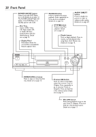
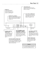
Rear Panel 21 MAINS jack Connect the supplied AC power cord here and to a standard AC outlet to supply power to the DVD Player. AUDIO OUT (Left/Right) Connect the supplied red and white audio cables here and to the Audio In jacks of a television or Stereo Receiver. Details are on pages 10-13. CVBS VIDEO OUT Connect the yellow video cable (supplied) here and to the TV's Video In jack. Details are on page 12. Pr/Cr Pb/Cb Y VIDEO OUT Connect an optional component video cable here and to the component Video In jacks of a TV. Details are on pages 10, 13-14. MAINS DIGITAL AUDIO OUT PCM/MPEG2/Dolby Digital/DTS COAXIAL OPTICAL SURROUND CENTER FRONT L 1 L R 2 R SURROUND SUB WF FRONT MULTICHANNEL AUDIO OUT AUDIO CVBS OUT Pr/Cr Pb/Cb Y VIDEO OUT S-VIDEO PROGRESSIVE SCAN OUT Pr/Cr Pb/Cb Y COAXIAL (DIGITAL AUDIO OUT) Connect an optional audio coaxial digital cable here and to the coaxial digital Audio In jack of a Stereo Receiver. Details are on page 14. MULTICHANNEL AUDIO OUT (CENTER, FRONT, SURROUND, and SUB WF) Connect these jacks to the corresponding In jacks on your multichannel receiver (not supplied). Refer to the multichannel receiver manual for details. OPTICAL (DIGITAL AUDIO OUT) Connect an optional audio optical cable here and to the optical digital Audio In jack of a Stereo Receiver. Details are on page 14. When the OPTICAL jack is not in use, replace its protective cap. Pr/Cr Pb/Cb Y PROGRESSIVE SCAN OUT Connect an optional component video cable here and to the component Progressive Scan Video In jacks of a TV. Details are on pages 10, 13-14. S-VIDEO (VIDEO OUT) Connect an optional S-Video cable here and to the S-Video In jack of a television. Details are on page 11. Caution • Do not touch the inner pins of the jacks on the rear panel. Electrostatic discharge may cause permanent damage to the unit.
-
 1
1 -
2
-
3
-
4
-
5
-
6
-
7
-
8
-
9
-
10
-
11
-
12
-
13
-
14
-
15
-
 16
16 -
 17
17 -
 18
18 -
 19
19 -
 20
20 -
 21
21 -
 22
22 -
 23
23 -
 24
24 -
 25
25 -
 26
26 -
27
-
28
-
29
-
30
-
31
-
32
-
33
-
34
-
35
-
36
-
37
-
38
-
39
-
40
-
41
-
42
-
43
-
44
-
45
-
46
-
47
-
48
-
49
-
50
-
51
-
52
-
53
-
54
-
55
-
56
 |
 |
