Pioneer DEQ-P9 Owner's Manual - Page 54
Connection Diagram
 |
View all Pioneer DEQ-P9 manuals
Add to My Manuals
Save this manual to your list of manuals |
Page 54 highlights
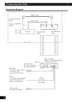
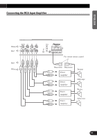
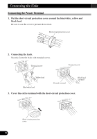
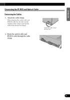
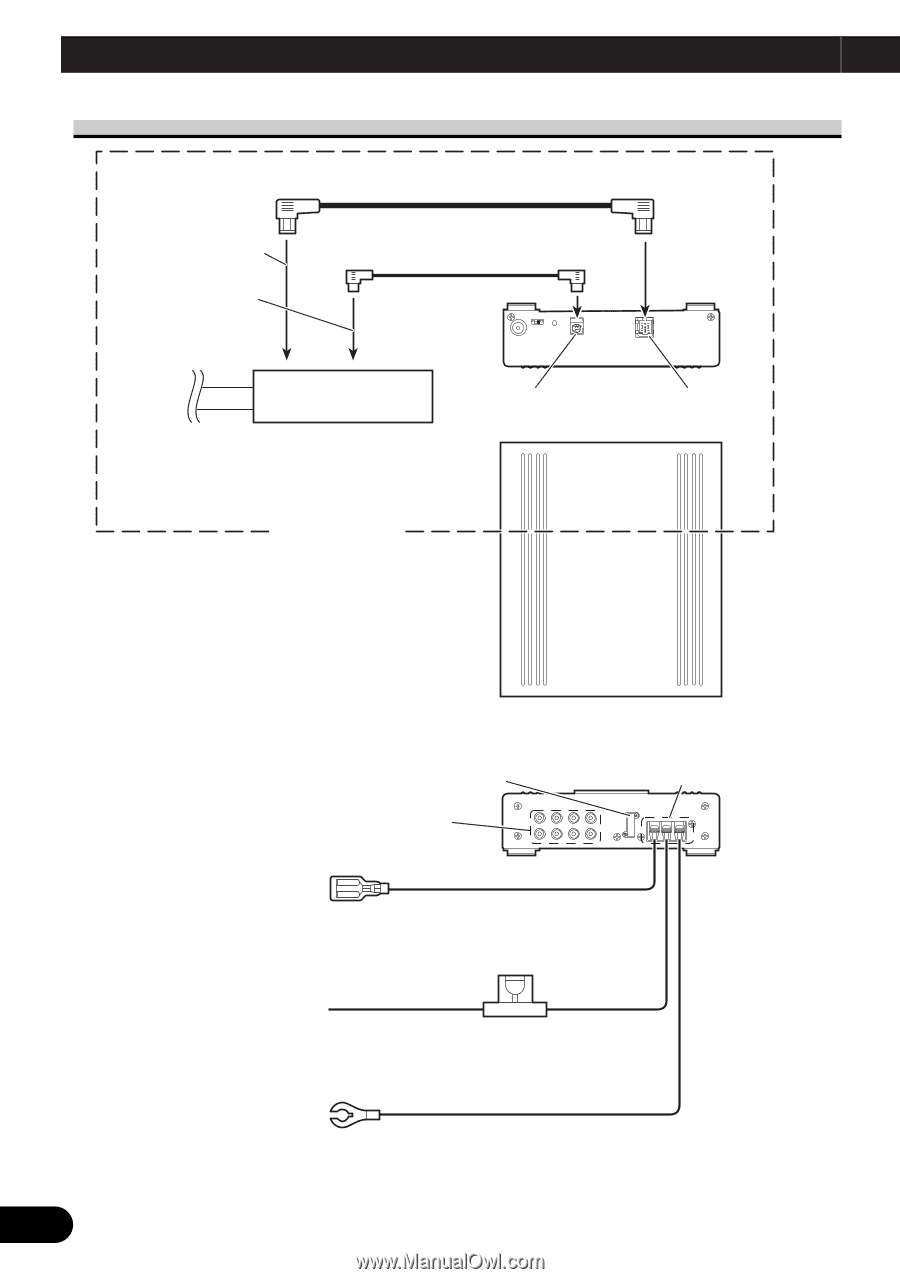
Connecting the Units Connection Diagram To IP-BUS OUTPUT (black) To Optical OUTPUT (black) IP-BUS cable optical cable DEX-P9 Optical INPUT (blue) IP-BUS INPUT (blue) Audio system Fuse (4A) RCA OUTPUT See "Connecting the RCAInput Amprifier." Blue/white To system control terminal of the power amp (max. 300 mA 12 V DC). Power Terminal Refer to "Connecting the Power Terminal" on page 51. Yellow To terminal always supplied with power regardless of ignition switch position. Fuse holder Black (ground) To vehicle (metal) body. 53
-
 1
1 -
2
-
3
-
4
-
5
-
6
-
7
-
8
-
9
-
10
-
11
-
12
-
13
-
14
-
15
-
16
-
17
-
18
-
19
-
20
-
21
-
22
-
23
-
24
-
25
-
26
-
27
-
28
-
29
-
30
-
31
-
32
-
33
-
34
-
35
-
36
-
37
-
38
-
39
-
40
-
41
-
42
-
43
-
44
-
45
-
46
-
47
-
48
-
 49
49 -
 50
50 -
 51
51 -
 52
52 -
 53
53 -
 54
54 -
 55
55 -
 56
56 -
 57
57 -
 58
58 -
 59
59 -
60
-
61
-
62
-
63
-
64
 |
 |
53
Connection Diagram
Optical INPUT
(blue)
IP-BUS INPUT
(blue)
IP-BUS cable
optical cable
DEX-P9
To IP-BUS OUTPUT
(black)
To Optical OUTPUT
(black)
Audio system
Fuse (4A)
Fuse holder
Power Terminal
Refer to
“
Connecting the Power
Terminal
”
on page 51.
Yellow
To terminal always supplied
with power regardless of
ignition switch position.
Black (ground)
To vehicle (metal) body.
Blue/white
To system control terminal
of the power amp
(max. 300 mA 12 V DC).
RCA OUTPUT
See
“
Connecting the
RCAInput Amprifier.
”
Connecting the Units