Sharp AL 1661CS AL-1661CS Facsimile Operation Manual - Page 17
Initial Settings
 |
UPC - 074000074606
View all Sharp AL 1661CS manuals
Add to My Manuals
Save this manual to your list of manuals |
Page 17 highlights
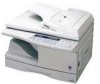
2 Chapter 2 INITIAL SETTINGS PART NAMES The following illustration shows the part names of the AL-1661CS. RSPF Reversing tray Original guides Document 1 feeder cover 2 Exit area Document feeder tray 3 5 4 Bypass tray TEL TEL jack LINE jack LINE 9 1 Document glass 2 Operation panel 3 Front cover 4 Paper tray 5 Bypass tray paper guides 6 7 8 9 10 6 Paper output tray 7 Paper output tray extension 8 Power switch 9 Handles 10 Power cord 13
-
 1
1 -
2
-
3
-
4
-
5
-
6
-
7
-
8
-
9
-
10
-
11
-
 12
12 -
 13
13 -
 14
14 -
 15
15 -
 16
16 -
 17
17 -
 18
18 -
 19
19 -
 20
20 -
 21
21 -
 22
22 -
23
-
24
-
25
-
26
-
27
-
28
-
29
-
30
-
31
-
32
-
33
-
34
-
35
-
36
-
37
-
38
-
39
-
40
-
41
-
42
-
43
-
44
-
45
-
46
-
47
-
48
-
49
-
50
-
51
-
52
-
53
-
54
-
55
-
56
-
57
-
58
-
59
-
60
-
61
-
62
-
63
-
64
-
65
-
66
-
67
-
68
-
69
-
70
-
71
-
72
-
73
-
74
-
75
-
76
-
77
-
78
-
79
-
80
-
81
-
82
-
83
-
84
-
85
-
86
-
87
-
88
-
89
-
90
-
91
-
92
-
93
-
94
-
95
-
96
-
97
-
98
-
99
-
100
 |
 |

13
2
Chapter 2
INITIAL SETTINGS
PART NAMES
The following illustration shows the part names of the AL-1661CS.
Document glass
Operation panel
Front cover
Paper tray
Bypass tray paper guides
Paper output tray
Paper output tray extension
Power switch
Handles
Power cord
RSPF
Exit area
Reversing tray
LINE
TEL
2
3
4
1
5
6
7
8
9
TEL jack
LINE jack
Bypass tray
Original guides
Document feeder tray
Document
feeder cover
10
9
1
2
3
4
5
6
7
8
9
10