Sharp ER-A450T Service Manual
Sharp ER-A450T Manual
 |
View all Sharp ER-A450T manuals
Add to My Manuals
Save this manual to your list of manuals |
Sharp ER-A450T manual content summary:
- Sharp ER-A450T | Service Manual - Page 1
SERVICE MANUAL ELECTRONIC CASH REGISTER MODEL ER-A450T SRV Key : LKGIM7113RCZZ PRINTER : PR-45M ("U" and "A" version) CAUTION EXTREME CAUTION MUST BE TAKEN WHEN SERVICING THIS MACHINE. WHEN THE MODE SWITCH IS IN THE OFF POSITION, VOLTAGE IS STILL SUPPLIED TO THE ENTIRE MACHINE. WHEN WORKING ON THIS - Sharp ER-A450T | Service Manual - Page 2
W Operating: 37 W (max.) 32 - 104 °F (0°C - 40°C) paper feed key Numeric keys Decimal point key Multiplication / Split-pricing key Clear key Department keys PLU / Subdepartment key Tax 1 shift key Tax 2 shift key UPC key Slip print key Percent 1 key Cashier code 2 - 5 keys Cash total 2 key Currency - Sharp ER-A450T | Service Manual - Page 3
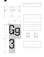
-2 8 For UPC code entry Scale entry 7 Item unit price 5. Specifications 1) Printer (PR-45M) • No. of station: • Validation: • Printing system: • No. of dot: • Dot pitch: • Font: • Printing capacity: • Character size: • Print pitch: • Print speed: • Paper feed speed (Manual feed): • Reliability - Sharp ER-A450T | Service Manual - Page 4
0.125 4 4.5 44.5±0.5 44.5±0.5 • Print format: 1.5 (12dots) (Units : mm) 1.5 (12dots) 0.125 0.125 2) Paper Item Name Roll dimension Thickness 3) Cutter • Method: Manual Description Heat-quality paper 44.5 ±0.5 mm in width 0.06 mm to 0.08 mm 6. Drawer 1) Specification (1) Drawer box and - Sharp ER-A450T | Service Manual - Page 5
selected between the /CI signal and the +5V signal by changing the connection of the SW2 (initial value: /CI signal) NOTE: Optional bar code reader: When connecting an ER-A6HS1, connect it to the Port 1 (or 2) and switch the No.9 pin signal to the +5V signal. When connecting other RS232 devices to - Sharp ER-A450T | Service Manual - Page 6
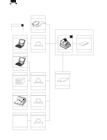
PURCHASE LOCAL PURCHASE BARCODE READER LOCAL PURCHASE RS-232 2por t ER-A450T COMPUTER PC UTILITY CABLE MASTER MA CHINE ER-03RA OPTION RAM ER-02FD EXE or ER-01/02FD LOCAL PURCHASE 3.5 inch FDD LOCAL PURCHASE CABLE LOCAL PURCHASE ER-04D W REMOTE DRA WER SLIP PRINTER LOCAL PURCHASE CABLE - Sharp ER-A450T | Service Manual - Page 7
tools No. NAME 1 RS-232 LOOP BACK CONNECTOR 2 KEY TOP REMOVER 3 2 × 2 KEY TOP INSTALLING JIG PARTS CODE 5. Supplies No. 1 Thermal roll paper 2 Thermal roll paper NAME PARTS CODE DESCRIPTION 512K bytes RAM CHIP FD unit 1 × 1 KEY TOP UNIT 1 × 2 KEY TOP UNIT 2 × 2 KEY TOP UNIT 1 × 1 DUMMY KEY - Sharp ER-A450T | Service Manual - Page 8
1. SERVICE reset (Program Loop • MRS-2 Used to clear all memory and keyboard contents. This reset returns all programming back to defaults. The keyboard must key setup procedure] MRS-2 0 executed Key position set *2 Free key 0 *1 Disable Free key setup complete. NOTES: 1: When the 0 key is - Sharp ER-A450T | Service Manual - Page 9
CHAPTER 4. HARDWARE DESCRIPTION 1. Hard ware block diagram DRAWER CPU STA NDARD RAM1 256KB OPTIONAL RAM2 ER-03RA:512KB 512KB TPRC1 GATE ARRAY MPCA7 PRINTER PR-45M OPC2 STA NDARD ROM 512KB CKDC8 RS232 I/F 1 ports OPERATER DISPLAY 1 LINE 7SEG 10DIG CUSTOMER DISPLAY 1 - Sharp ER-A450T | Service Manual - Page 10
VSS 20 A0 21 A1 22 A2 23 A3 24 A4 25 A5 26 A6 27 A7 28 A8 29 A9 30 A10 31 A11 32 A12 33 A13 34 A14 35 A15 36 VSS 37 A16 38 A17 39 A18 40 A19 41 A20 42 A21 43 A22 44 A23 - Sharp ER-A450T | Service Manual - Page 11
dog timer H8/500 CPU DTC Interruption controller Refresh controller Wait state controller A/D convertor 16bit free running timer x 2ch 8bit timer Serial communication interface x 2ch Port 8 Port 7 Port RR/P64 CD/P63 CS/P62 DR/P61 ER/P60 STOP/P57 P56 FMRS P54 P53 P52 P51 P50 Fig. 2-2 4 - 3 - Sharp ER-A450T | Service Manual - Page 12
A7 29 A8 30 A9 31 A10 32 A11 33 A12 34 A13 35 A14 (to CKDC) SHIFT ENABLE (from CKDC) FISCAL MEMORY RESET (Nu) FISCAL MEMORY BUSY (Nu) FISCAL MEMORY READY (Nu) POP-UP DISPLAY SENSOR (Nu) IN Nu (GND) OUT Nu (GND) OUT Nu (GND) OUT ER signal for RS232 (Equipment Ready) IN DR signal for RS232 (Data - Sharp ER-A450T | Service Manual - Page 13
VCC 20 GND 21 NU 22 VRESC 23 SLTMG 24 SLRST 25 AS 26 RD 27 WR 28 PHAI 29 SDT7 30 SDT6 31 SDT5 32 GND 33 SDT4 34 SDT3 35 SDT2 36 SDT1 37 D0 38 D1 39 D2 40 D3 41 GND 42 D4 43 158 TWAIT D5 - Sharp ER-A450T | Service Manual - Page 14
POFF MD0 MD1 WAIT EXWAIT RJRST SLRST *PRST RJTMG SLTMG PTMG Address decode External CS Internal CS RASEL Image control SSP comparison register BAR. SSPRQ Buffer Read/write control WAIT control CAPS select Print gate I/R Control IRTX IRRX RCI ASKRX Φ Divider CHS serial select Multiplexer - Sharp ER-A450T | Service Manual - Page 15
SLTMG 25 SLRST 26 AS 27 RD 28 WR 29 φ 30 SDT7 31 SDT6 32 SDT5 33 GND 34 SDT4 35 SDT3 36 SDT2 37 SDT1 38 D0 39 D1 48 RESET 49 SHEN 50 INT3 In/ Out Function Out Receipt side paper feed solenoid (NU) Out Journal side paper feed solenoid (NU) Out Printer partial cut signal (NU) Out Printer - Sharp ER-A450T | Service Manual - Page 16
chip select signal Out ROM 2 chip select signal (NU) Out RAM 2 chip select signal Out RAM 1 chip select signal In Printer reset signal In FOR TPRC (NU ST5 23 VDD 24 GND 25 NU 26 KR0 27 KR1 28 KR2 29 KR3 30 KR5 31 KR6 32 2) Pin assignment (CKDC8) Pin No. SYMBOL 1 DP 2 A 3 B 4 C 5 D - Sharp ER-A450T | Service Manual - Page 17
34 AVRF GND 35 AVDD VDD 36 /RESET /RES0 IN 37 XT2 38 XT1 32.768 KHz 39 IC GND 40 X2 41 X1 4.19 MHz 42 VSS1 GND 43 TPRC1 SO CLOCK SI LATCH ST1~4 HCD PHUP,PSP, PST,POP Thermal head Switch sensor PB RAM (SRAM) Fig. 2-6 The CPU is designed for use with H8/500. The bus I/F, - Sharp ER-A450T | Service Manual - Page 18
VCC 20 VCC 21 VCC 22 VCC 23 TEST1 24 D0 25 D1 26 D2 27 D3 28 D4 29 GND 30 GND 31 GND 32 D5 33 D6 34 D7 35 A0 36 A1 37 A2 38 NU 39 INTI 40 WI 41 BACK 42 A3 43 158 RESET A4 - Sharp ER-A450T | Service Manual - Page 19
thermalhead Data from PB-RAM or zero data are GND 31 GND 32 GND 33 register, print buffer data IO I/O Data bus 1: Internal register, print buffer data IO I/O Data bus 2: Internal register, print buffer data IO I/O DAta bus 3: Internal register, print buffer data IO I/O Data bus 4: Internal register - Sharp ER-A450T | Service Manual - Page 20
73 WR I Write strobe signal: Write enable into the internal register and the print buffer. 74 AS I AS 75 POF I Power paper feed pulse motor drive signal, phase A - GND - GND - GND O NU O PB-RAM write strobe signal O PB-RAM read strobe signal O NU O Address 14 for PB-RAM O Address 13 for PB-RAM - Sharp ER-A450T | Service Manual - Page 21
bus 6 for PB-RAM O Address bus 5 for PB-RAM O Address bus 4 for PB-RAM O Address bus 3 for PB-RAM O Address bus 2 for PB-RAM O Address bus 1 for PB-RAM I TPRC1 clock input pin 27 RCVRDY1 28 TRNRDY1 29 /CTS1 30 RCVDT1 31 /CI1 32 /RTS1 33 /CS1 34 /CD2 35 TRNEMP2 36 RCVRDY2 37 - Sharp ER-A450T | Service Manual - Page 22
IS RS-232 control signal /CD input Pin NO. Name 26 BRK1 27 TRNEMP1 28 RCVRDY1 29 TRNRDY1 30 /CTS1 31 RCVDT1 ER-A770 BRK2 TRENMP2 RCVRDY2 TRNRDY2 /CTS2 RCVDT2 32 /CI1 /CI2 33 /RTS1 /RTS2 34 /CS1 /CS2 35 /CD2 VCC 36 TRNEMP2 TRENMP3 37 RCVRDY2 RCVRDY3 38 TRNRDY2 TRNRDY3 39 - Sharp ER-A450T | Service Manual - Page 23
DATA BUS (USART) 98 /R /RDH O Read signal (to USART) Pin NO. Name ER-A770 I/O Description 99 /W /WRH O Write signal (to USART) 100 VCC VCC +5V RS-232 transmission buffer empty signal 117 SYCBKA BRK1 IO Break code detection signal 118 GND GND GND 119 /CSB /CS2 IS - Sharp ER-A450T | Service Manual - Page 24
159 160 I ID IS ISU IO 3S ON6 Name ER-A770 I/O VCC VCC GND GND /CSD VCC IS C106 18P X1 4.19MHz 1 2 3 R164 330K X2 32.768KHz C105 33P Fig. 3-2 Two oscillators are connected to program and immediately executes the power-off program to save the data in the CPU registers in the external S-RAM - Sharp ER-A450T | Service Manual - Page 25
area: Image is formed in RAM area address 1F0000H to 1F7E7FH. ( Note) Note: Image can be formed in lower 32KB of RAS2. ROM area memory map C00000H ROS1 (512K Byte) C00000H ROM area (3M byte) FFFFFFH Expansion I/O area (1M byte) Fig. 5-1 ( 1) "Internal I/O" means the registers in the H8/510 - Sharp ER-A450T | Service Manual - Page 26
board detection signal incorporated in the option slot. Note used in the ER-A445P. (Not used) Access is performed with two ROM chip select Access is performed with two RAM chip select signals, RAS2 and RAS3. The control register in MPCA7 allows selection of page image memory area. (RAS1 is selected - Sharp ER-A450T | Service Manual - Page 27
employed for implementing the Special Service Preset(SSP). (Block diagram) NMI SSPRQ As the address detection system, the break address register comparison system is employed though the mapping system and employed in the conventional monitor RAM. The address register located in MPCA is always - Sharp ER-A450T | Service Manual - Page 28
which break register the SSP break is detected and is read as binary data by reading address FFFFFFH (*1). If there are 32 break registers, the the thermal printer controller (TPRC1). The PB-RAM connected to TPRC1 serves as a print data buffer. 2) Paper feed circuit TPRC1 RAS/JAS RBS/JBS RCS/JCS - Sharp ER-A450T | Service Manual - Page 29
to the CPU through MPCA6. 3) Print circuit PB RAM STRB1~STRB5 TPRC 1 LATCH SO SI CLOCK VHCOM solenoid Fig. 8-1 The drawer is directly supported by the CPU. No action starts when on sequence During service interruption, the CKDC8 senses POF within 500msec. When service interruption is cancelled - Sharp ER-A450T | Service Manual - Page 30
sec Fig. 9-3 When the CPU senses a service interruption or an error, it performs the necessary procedure for the charge, Battery Back-up power, CKDC-8 Back-up power VCH: Fiscal memory unit (Not in "U" and "A") RES1 110±10msec Fig. 9-4 3) paper feed key. KR11 is used as the return signal of the mode - Sharp ER-A450T | Service Manual - Page 31
machine functions in the field. The program is contained within the ER-A450S. The diagnostic program is stored in the external ROM which /RAM must be working properly. 2. Operational procedure To start the diagnostic program, you must enter the following command. SRV mode : XXX CA/AT Test code - Sharp ER-A450T | Service Manual - Page 32
R J 63 62 61 52 51 74 43 33 42 32 41 ER-A450T 2254 2) Functional description The keyboard test is performed with the sum check data of the key code not, the error print is made. The sum check data is obtained by totalizing all key hardware codes except for the - Sharp ER-A450T | Service Manual - Page 33
08 The following message on the front display is displayed. 1 0 4 Key code 3) Check items a) Check of the display in the test and the content of end 1 0 5 Error E----- 1 0 5 [6] Printer sensor test 1) Key operation 106 CA/AT 2) Functional description State of the paper near end sensor is - Sharp ER-A450T | Service Manual - Page 34
and the test No. and message is printed Normal end 1 0 9 Error E----- 1 0 9 SSP table full F----- 1 0 9 In this SSP for the SSP check, F-print is performed to terminate the program without check. 3) Check items X Description O Drawer open sensor RAM test 1) Key operation 120 CA/AT 5 - 4 - Sharp ER-A450T | Service Manual - Page 35
Error termination print E - - - - ROM1 130 27040 Note: " " means the ROM version number. The underlined section (10 bytes) of code Test termination print [14] Option RAM test 1) Key operation 200 CA/AT JOB #NO. 200 RAM NO. Option RAM Memory to be checked ER-03RA Address area to be checked - Sharp ER-A450T | Service Manual - Page 36
comparison, data "AAAAH" write PASS5: Data "AAAAH" read and comparison PASS6: Memory data restore If a compare error is found in the check sequence from PASS1 to PASS6, the error print (error code E1) is performed. If there is no error found to the end of the last address, the operation is completed - Sharp ER-A450T | Service Manual - Page 37
check , or terminates, the termination printout occurs irrespective of any errors that have occurred during the check. (The program terminates normally only when no error print-out has occurred.) ERROR ERROR PRINT Contents 1 E1-ER DR ERn-DRn ERR 2 E2-ER CI ERn-CIn ERR 3 E3-RS CD RSn-CDn ERR - Sharp ER-A450T | Service Manual - Page 38
CHAPTER 6. DOWN LOAD FUNCTION 1. General RAM data can be transmitted in the following two methods. Save the data before servicing as follows: ECR ECR • Cable: 9 pin D-SUB - 9 pin D-SUB ECR ECR Fig. 1-1 ECR ER-02FD • Cable: 9 pin D-SUB - 25 pin D-SUB ECR ER-02FD Fig. 1-2 2. SIO interface - Sharp ER-A450T | Service Manual - Page 39
SUB ER- memory to be transmitted in ASCII number. Sum check End code: Hex 0D NOTE: • In order that contents of RAM memory may avoid over-riding pages for this job, the RAM RAM DATA FORMAT Exhibit: BD 7E 83 FC 03 B6 42 44 37 45 38 33 46 43 30 33 42 36 Code table HEX 0 1 2 3 4 5 6 7 ASCII 30 31 32 - Sharp ER-A450T | Service Manual - Page 40
error) 5: Hard ware error 6: Power off error 7: Time out error 11: Application error (Transmit data size error) 12: Application error (Block sequence error) 7) Service reset the receiving ECR. 8. Saving/Loading of data to/From the FD unit Configuration 1) Turn off the power switch of the ER - Sharp ER-A450T | Service Manual - Page 41
RS-232 interface of the PC. ER-A450T No Procedure on P.C. side 1 Install "02FD.EXE" on the P.C. ALL RAM Data UpLoad : Go to "2" ALL RAM Data DownLoad : Go to "9" 2 ALL RAM Data UpLoad ( ER-A450T -> PC ) 3 "Execute "02FD.EXE" on P.C" *Don' t execute the other Software at the same time. Channel - Sharp ER-A450T | Service Manual - Page 42
00000 CA/AT 8 UpLoad is completed. The initial Window is shown. "Push "Exit" Button." 9 ALL RAM Data Download ( PC -> ER-A450T ) 10 Execute "02FD.EXE" on P.C *Don' t execute the other Software at the same time. 8 UpLoad is completed. 9 Place the SRV key in the SRV mode. 11 Set the Communication - Sharp ER-A450T | Service Manual - Page 43
by the programming. E04 Joumal paper is nearly empty. Replace joumal paper roll with a new one. E05 Secret code error Enter a correct secret code. E07 Memory is full. Expand the file within the capacity of memory. E08 Insert slip paper. Insert slip paper. E09 Invalid cashier code is enterd - Sharp ER-A450T | Service Manual - Page 44
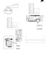
8 7 6 5 4 CHAPTER 8. CIRCUIT DIAGRAM & PWB LAYOUT 1. MAIN PWB CIRCUIT DIAGRAM POWER SUPPLY(MAIN PWB) D +24V F1 HEAT SINK Q23 C4153 L1 CN8 +24V GND 1 2 PS CN FROM PS PWB C FUSE UL. CSA 1A/125V C266 100uF 50V C84 0.1uF 50V IC6 6 1 5 7 2 8 3 4 KA34063 C85 220P R111 10 - Sharp ER-A450T | Service Manual - Page 45
100 R146 19 20 21 22 23 24 25 26 27 28 29 30 31 32 33 34 35 36 37 38 39 40 41 42 43 44 45 46 47 3-8B 6-2C 3-8B R148 16K"F" R147 3.6K"F" C100 C +24V /RI /RSS /CDS /CSS /DRS /ERS +5V NU 10-7C +5V +5V R137 10K R138 10K /PRST 3-4A /PTMG 3-4A R153 10K R152 10K - Sharp ER-A450T | Service Manual - Page 46
10K A23 A IC10 1 2 3 4 5 6 7 8 9 10 11 12 13 14 15 16 17 18 19 20 21 22 23 24 25 26 27 28 29 30 31 32 33 34 35 36 37 38 39 40 41 42 43 44 45 46 47 48 49 50 51 52 53 54 55 56 57 - Sharp ER-A450T | Service Manual - Page 47
8 7 6 5 FMC (NOT USED) D +24 IC11 KIA7812 C 1 3 Q24 KTA1664 C173 0.1u/50V 2 VR1 5K R232 820 R241 68 "F" C171 0.1u/50V R233 1.2K C172 10u/50V R234 3.3K +5V B R235 3.9K Q25 A1036 JP2 Q26 KRC106S R236 A 10K 8 7 6 5 4 3 2 1 4/12 D +5V +5V +5V +5V R237 56K R238 - Sharp ER-A450T | Service Manual - Page 48
8 7 6 5 MEMORY 2-1D 2-1D 2-8C /RD /WR A[0..18] 2-8D D[0..7] 4-7D 3-8C +5V C177 0.1u D C176 47U/16V IC13 8 9 10 11 12 VPP A16 A15 A12 A7 A6 A5 A4 A3 A2 A1 A0 VCC A18/PGM A17 A14 A13 A8 A9 A11 32 31 30 29 28 27 26 25 A18 A17 A14 A13 A8 A9 A11 4M OE A10 CE 24 23 22 A10 D0 D1 D2 - Sharp ER-A450T | Service Manual - Page 49
8 7 6 5 4 3 OPTION MEMORY/OPT CN D A[0..18] C B D[0..7] +5V IC16 RAM A18 A16 A14 A12 A7 A6 A5 A4 A3 A2 A1 A0 1 2 3 4 5 6 7 8 8 9 10 11 12 13 14 15 16 17 18 19 20 21 22 23 24 25 26 27 28 29 30 31 32 33 34 GND GND +5V +5V VDD /WR0 /RESET /RD0 /TRQ1 /RES /IRQ1 /POFF /EXINT0 /OPTCS A0 A1 A2 - Sharp ER-A450T | Service Manual - Page 50
39 A11 38 A12 A13 37 36 A14 35 A15 34 A16 BHE 33 32 VSS 31 D15/A-1 30 D7 D14 D6 29 28 27 D13 26 D5 330P 4 0.1uF R339 100K /RPES 6-4B +5V R304 IC26 1 R340 100K 2 C268 0.1uF BA1 RAM(256K) 240 3 BA2 SOP C228 BA3 1000P KIA431A BA4 BA5 BA6 BA7 BA8 BA9 BA10 BA11 BA12 2-1C - Sharp ER-A450T | Service Manual - Page 51
G3 G2 G1 VDD G[1..10] C10 27p R6 G10' G9' G8' G7' G6' G5' G4' G3' G2' G1' G[1'..10'] C1 10U/16V 330K X2 C11 32.768KHZ 22p +5V TO POP UP LED PWB CN3 1-1A /POFF 9-8B KR5 C 9-8B KR6 9-8B KR7 BD10 VDD BD9 BD8 VDD R1 D1 10K - Sharp ER-A450T | Service Manual - Page 52
A 15 16 17 18 19 20 21 22 23 24 25 26 27 28 29 30 31 32 33 34 35 36 37 38 39 40 41 42 43 44 45 46 47 48 49 50 ST1 ST1A 4 4 49 48 34 21 20 7 5 35 D17 ST2 ST2A 5 5 47 46 32 19 18 6 4 33 D18 ST3 ST3A 6 6 45 44 30 17 16 NC 3 NC - Sharp ER-A450T | Service Manual - Page 53
A1 A[0..5] VCC IC29 1 2 3 4 5 6 7 8 9 10 11 12 13 14 15 16 17 18 19 20 21 22 23 24 25 26 27 28 29 30 31 32 33 34 35 36 37 38 39 40 41 42 43 44 45 46 47 48 49 50 51 52 53 54 55 56 57 - Sharp ER-A450T | Service Manual - Page 54
18 24 /EN 1 /SHDN 25 0 1 MAX211 0 +5V C255 0.1U C254 0.1U ICP O OHM CN21 /CD 1 /CD /DR RD /RS SD /CS /ER /CI 2 3 4 5 6 7 8 9 10 /DR RD /RS SD /CS /ER /CI +5V GND RS CN FB6 FB7 FB8 R334 FB1 R335 FB2 R336 FB3 R337 FB4 R338 FB5 100X5 C246 C247 C248 - Sharp ER-A450T | Service Manual - Page 55
8 7 6 5 4 3 2 1 RS232C CONNECTOR (RSCN2) 12/12 D C /RTS1 /DTR1 TXD1 RCVDT1 /DCD1 /CI1 /DSR1 /CTS1 B /RTS1 /DTR1 TXD1 RCVDT1 /DCD1 /CI1 /DSR1 /CTS1 C292 0.1U C309 0.1U VCC C311 0.1U 1 1 IC31 12 C1+ V C 14 C1- C V+ 13 15 C2+ V- 17 16 C2- 7 T1IN T1OUT 2 6 T2IN - Sharp ER-A450T | Service Manual - Page 56
2. MAIN PWB LAYOUT (1) SIDE A - Sharp ER-A450T | Service Manual - Page 57
(2) SIDE B - Sharp ER-A450T | Service Manual - Page 58
8 7 6 5 3. FRONT PWB/POP UP PWB CIRCUIT DIAGRAM D G10' G9' G8' G7' G6' G5' G4' FND5 FND4 FND3 FND2 4 G3' G2' G1' FND1 3 G1'..G10' R8 R7 R6 R5 R4 R3 R2 R1 C 30 30 30 30 30 30 30 30 DP' G' F' E' D' C' B' A' A'..DP' 2 CN1 1 2 3 4 5 6 7 - Sharp ER-A450T | Service Manual - Page 59
4. FRONT DISPLAY PWB LAYOUT 5. POP-UP DISPLAY PWB LAYOUT - Sharp ER-A450T | Service Manual - Page 60
7 423 LM2574HVN 6,8PIN:NC HEAT SINK L1 180uH R2 10 D2 PS156R R3 22KF R4 1.2KF C4 2200uF/50V +24V 2 +24V 1 GND C TO MAIN PWB |LINK |450CKDC.SCH |450CPU.SCH |450FMC.SCH |450FRT.SCH |450GA.SCH |450KEY.SCH |450MM.SCH |450OM.SCH B |450POP.SCH B |450POWER.SCH |450PR.SCH |450PS.SCH - Sharp ER-A450T | Service Manual - Page 61
7. PS PWB LAYOUT - Sharp ER-A450T | Service Manual - Page 62
PARTS GUIDE ER-A450TU/A MODEL ER-A450T PRINTER:PR-45M SRV KEY:LKGIM7113BHZZ CONTENTS (for U.S.A,Canada) 1 Exteriors 2 these parts with specified ones for maintaining the safety and performance of the set. This document has been published to be SHARP CORPORATION used for after sales service only - Sharp ER-A450T | Service Manual - Page 63
ER-A450TU/A 1 Exteriors NO. PARTS CODE 1 PFILW6976BHSA 2 GCABB7861BHZZ 5 CPWBF7504BH01 6 PFILW6961BHSF 7 QCNW-7878BHZZ 8 GCABB7857BHZE 9 2 4 2 1 B H Z Z 30 Q C N W - 7 8 7 2 B H Z Z 31 L B N D J 2 0 0 3 S C Z Z 32 X N E S D 3 0 - 2 4 0 0 0 34 X H B S D 3 0 P 0 4 0 0 0 35 Q T A N Z 6 6 6 Paper - Sharp ER-A450T | Service Manual - Page 64
1 Exteriors ER-A450TU/A 49 1 48 70 2 8 9 5 7 6 45 75 46 62 39 75 76 44 44 34 43 41 63 34 41 19 27 20 21 28 31 22 18 67 29 68 30 32 10 72 13 74 17 18 14 B 77 64 18 16 34 A 18 18 18 18 18 23 18 38 66 71 66 65 34 35 B 18 18 - 2 - RCP00363 - Sharp ER-A450T | Service Manual - Page 65
ER-A450TU/A 2 Keyboard unit NO. PARTS CODE 1 LANGQ7604BHZZ 2 LKGIW0001BHZA 3 QCNW-7881BHZZ 5 XJPSD30P08000 LKGIM7111BHZZ 6 300mm) Instruction book E Instruction book E Instruction book F Vinyl bag (80×120mm) Lock key (1pc) OP key (OP) SM key (SM) MA key (MA) Caution card (Red) Caution card (Black - Sharp ER-A450T | Service Manual - Page 66
2 Keyboard unit 6 5 7 9 5 8 10 1 19 3 20 2 11 14 15 501 18 17 18 16 A 18 18 18 18 RCP00364 3 Packing material & Accessories ER-A450TU/A 11 12 15 14 10 19 20 1 7 6 2 5 18 3 13 - 4 - 4 RCP00365 - Sharp ER-A450T | Service Manual - Page 67
ER-A450TU/A 4 Drawer box unit (SK423 type) NO. PARTS CODE CCABM7862BHZA 1 CCABM7864BHZA 3 PGUMM6695BHZZ 4 NROLP6650BHZZ 0 - 5 0 0 0 0 30 X W S S D 6 0 - 1 5 0 0 0 GDRW-6680BHZZ 31 G D R W - 6 6 7 8 B H Z Z 32 G C O V A 7 1 4 6 B H Z Z 33 L K G I W 7 3 3 0 B H Z Z 34 P R N G T 6 6 3 7 Paper - Sharp ER-A450T | Service Manual - Page 68
4 Drawer box unit (SK423 type) ER-A450TU/A 15 1 22 25 26 16 17 18 23 24 29 30 28 59 60 25 39 37 3 4 5 5 5 58 7 504 5 8 9 10 27 15 503 13 14 28 30 29 21 20 11 31 32 33 34 36 35 502 38 42 5 5 57 for CANADA 501 505 for - Sharp ER-A450T | Service Manual - Page 69
ER-A450TU/A 5 Main PWB unit(include Block6) NO. PARTS CODE 1 PRDAF6656BHZZ 2 QCNCM1101BHZZ 3 QCNCM7057BHZZ 4 QCNCM7207BH4J 5 QCNCW6882BH1A 6 QCNCW7081BHZZ 7 QCNCW7118BH0I 8 TAL (32.768KHz) (UDZ5.1B) EPROM (4M)(27040RBX1A) IC (4AC16) S-RAM (1M SOP)(5108CP7H-1) IC (BA10393F) [Q23] [CN8] - Sharp ER-A450T | Service Manual - Page 70
5 Main PWB unit(include Block6) NO. PARTS CODE 57 V H I D 7 8 0 0 2 1 5 0 5 58 V H I F 2 5 8 0 2 4 P C / 59 V H I G 7 6 C 2 5 6 F 7 0 60 V H I H 6 4 1 5 1 0 8 1 0 61 V H I K A 3 4 0 6 3 A - 1 62 V H I K I A 4 3 1 Screw (M3×6) CL N E Main PWB unit ER-A450TU/A DESCRIPTION [IC2] [IC17] [IC21] [ - Sharp ER-A450T | Service Manual - Page 71
PWB unit(NORMAL) DESCRIPTION [CN1] [CN1] [FND1∼FND4] [R10,12,14,16,18,20,22,24] 10 Articles for consumption NO. PARTS CODE 1 TPAPR6645RC05 2 TPAPR6655RC05 PRICE RANK AY BA NEW MARK PART RANK S S DESCRIPTION Roll paper (5rolls/pack) Roll paper (5rolls/pack)(High preservation type) - 9 - - Sharp ER-A450T | Service Manual - Page 72
ER-A450TU/A 11 Service route options NO. PARTS CODE 1 LKGIM7113BHZZ 2 LKGIM7126BHZZ 3 GCOVH7126BHZZ DUNTK3677BH03 XEBSD30P08000 XHBSD30P04000 4 LX-BZ6778BHZZ QCNW-7895BHZZ QCNCM6865RC0B 5 GCOVB7153BHZZ 11 U K O G - 6 7 0 5 R C Z Z 12 U K O G - 6 6 3 4 R C Z Z 13 U K O G - 6 7 2 5 B H Z Z 101 D U - Sharp ER-A450T | Service Manual - Page 73
ER-A450TU/A s Index PARTS CODE [C] CCABM7862BHZA CCABM7864BHZA CCAS-6678BH01 CCAS- 11-101 AM S 4-901 BY E 4-901 BY E 1- 8 BD D 1- 2 AN D 4- 57 BC D 4- 12 AZ D 1- 48 AZ D 4- 32 AV D 11- 5 BH S 11- 3 BE S 1- 65 AT D 1- 21 AH D 1- 13 AH D 1- 63 AK D 4- 31 BF D 4- 31 - Sharp ER-A450T | Service Manual - Page 74
12 AX S 11- 11 BC S 11- 13 BB S 5- 29 AA C 5- 30 AA C 5- 31 AA C 5- 32 AC C 5- 33 AA C 5- 34 AA C 5- 35 AA C 5- 36 AB C 5- 37 AB C 5- 38 AB C 5- 46 AA C PARTS CODE VCKYTV1HF104Z VCQYNA1HM333K VHD1SR1544001 VHD1SS353//-1 XBPSD30P04000 XBPSD30P06000 " ER-A450TU/A NO. - Sharp ER-A450T | Service Manual - Page 75
ER-A450TU/A PARTS CODE XBPSD30P06K00 XEBSD30P08000 " XEBSD30P10000 XEBSD30P14000 XHBSD30P04000 " XHBSD30P12000 XHBSD40P06000 1- 18 11- 4 1- 41 1- 75 1- 34 11- 4 4- 26 1- 28 4- 39 4- 41 4- 60 2- 18 2- 5 1- 32 4- 24 4- 29 4- 20 4- 5 1- 16 4- 23 4- 30 PRICE RANK AA AA AA AA AA AA AA AA AA AA AA AA AA - Sharp ER-A450T | Service Manual - Page 76
. Printed in Japan. No part of this publication may be reproduced, stored in a retrieval system, or transmitted, in any form or by any means, electronic, mechanical, photocopying, recording, or otherwise, without prior written permission of the publisher. SHARP CORPORATION Information Systems Group
-
 1
1 -
 2
2 -
 3
3 -
 4
4 -
 5
5 -
 6
6 -
 7
7 -
8
-
9
-
10
-
11
-
12
-
13
-
14
-
15
-
16
-
17
-
18
-
19
-
20
-
21
-
22
-
23
-
24
-
25
-
26
-
27
-
28
-
29
-
30
-
31
-
32
-
33
-
34
-
35
-
36
-
37
-
38
-
39
-
40
-
41
-
42
-
43
-
44
-
45
-
46
-
47
-
48
-
49
-
50
-
51
-
52
-
53
-
54
-
55
-
56
-
57
-
58
-
59
-
60
-
61
-
62
-
63
-
64
-
65
-
66
-
67
-
68
-
69
-
70
-
71
-
72
-
73
-
74
-
75
-
76
 |
 |
SERVICE MANUAL
ELECTRONIC
CASH REGISTER
MODEL
ER-A450T
SRV Key : LKGIM7113RCZZ
PRINTER: PR-45M
("U" and "A" version)
CAUTION
EXTREME CAUTION MUST BE TAKEN WHEN SERVICING THIS MACHINE. WHEN THE
MODE SWITCH IS IN THE OFF POSITION, VOLTAGE IS STILL SUPPLIED TO THE ENTIRE
MACHINE.
WHEN WORKING ON THIS MACHINE MAKE SURE THAT THE POWER CORD IS
REMOVED FROM THE WALL OUTLET.
CHAPTER 1. SPECIFICATIONS
. . . . . . . . . . . . . . . . . . . . . . . . . . . . . . . . . .
1-1
CHAPTER 2. OPTIONS
. . . . . . . . . . . . . . . . . . . . . . . . . . . . . . . . . . . . . . . . .
2-1
CHAPTER 3. SERVICE RESET AND MASTER RESET . . . . . . . . . . . . . . . .
3-1
CHAPTER 4. HARDWARE DESCRIPTION . . . . . . . . . . . . . . . . . . . . . . . . . .
4-1
CHAPTER 5. TEST FUNCTION . . . . . . . . . . . . . . . . . . . . . . . . . . . . . . . . . . .
5-1
CHAPTER 6. DOWN LOAD FUNCTION
. . . . . . . . . . . . . . . . . . . . . . . . . . . .
6-1
CHAPTER 7. SERVICE PRECAUTION . . . . . . . . . . . . . . . . . . . . . . . . . . . . .
7-1
CHAPTER 8. CIRCUIT DIAGRAM & PWB LAYOUT . . . . . . . . . . . . . . . . . . .
8-1
PARTS GUIDE
SHARP CORPORATION
CONTENTS
This document has been published to be used
for after sales service only.
The contents are subject to change without notice.
Parts marked with "
" are important for maintaining the safety of the set. Be sure to replace these parts with specified
ones for maintaining the safety and performance of the set.