Sharp ER-A450T Service Manual - Page 36
] RS-232 Channel 1 check, 16] RS-232 channel 8 check
 |
View all Sharp ER-A450T manuals
Add to My Manuals
Save this manual to your list of manuals |
Page 36 highlights
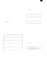
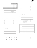
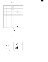
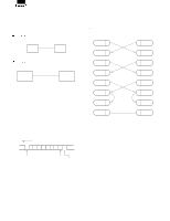
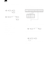
2) Content The following process is performed for memory addresses to be checked. PASS1: memory data save PASS2: Data "0000H" write PASS3: Data "0000H" read and comparison, data "5555H" write PASS4: Data "5555H" read and comparison, data "AAAAH" write PASS5: Data "AAAAH" read and comparison PASS6: Memory data restore If a compare error is found in the check sequence from PASS1 to PASS6, the error print (error code E1) is performed. If there is no error found to the end of the last address, the operation is completed normally. Then the following address check is performed. " " shows a valid address, and "!" shows an invalid address. In case of an error, the error code E2 is printed. Check Address 200000H 200001H 200002H 200004H 200008H 200010H 200020H 200040H 200080H 200100H 200200H 200400H 200800H 201000H 202000H 204000H 208000H 210000H 220000H 240000H 260000H 7-SEGMENT DISPLAY: 2 0 0 3) Check the following items. Check the termination print. 4) Test termination The test terminates after printing the termination message. Termination print E1--E2--- 200 (data check error) 200 (address check error) 200 (normal end) : Error address [15] RS-232 Channel 1 check [16] RS-232 channel 8 check Loop back connector for D-SUB 9pin : UKOG-6705RCZZ PIN No. 123456789 SIGNAL NAME CD RD SD ER GND DR RS CS CI 1) Key operation check The program is activated by JOB#501 or JOB#550 SRV mode: 501 CA/AT : Channel 1 550 CA/AT : Channel 8 2) Functional description If the channel specified by the JOB#CODE is not set, the machine will result in a misoperation. When the channel is set, the machine conducts the loop check concerning the channel specified by JOB#CODE by using the loopback connector. The following three items are checked: Control signal check Data transfer check Timer check (RS-232 onboard timer) Check Control signal check (ERn-DRn•CIn, RSn-CDn•CSn loop check) OUTPUT ERn RSn OFF OFF OFF ON ON OFF ON ON DRn OFF OFF ON ON INPUT CIn CDn OFF OFF OFF ON ON OFF ON ON CSn OFF ON OFF ON The read check about the above INPUT items and interrupt check of CS, CI and CD are performed. Read check: ER and RS are switched over in the order as shown in the above table to confirm the logic of DR, CI, CD and CS.If the read logic is different from the one in the table, error print-outs occur. Interrupt check: Allows the interruption of either of CS, CI and CD one by one. (The mask is released.) The interruption does not take place when each signal is turned on. Or if the interruption occurs when a signal is turned off, error print-outs occur. Each of the above checks should be made in four cycles. Check Data transfer check (SDn-RDn loop check) In this check, a transfer of 256-byte loopback data of $00∼ $FF. Note) The above check should be made with the baud rate set at 9600BPS. Check Timer check Before making check , set the corresponding timer at 10ms for RCVDT activation, and check to see that: 1) TRQ1 is not generated during the execution of check . 2) TRQ1 is generated in 10msec. after check ished. is fin- 3) Check the followin item If an error occurs during the above checks, the following error printouts occur. Even if an error occurs during check , the test is continued after the corresponding error print-out has occurred. An error occurs during the execution of check or , the test is terminated after the corresponding error print-out has occurred. 5 - 6
-
 1
1 -
2
-
3
-
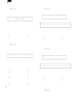
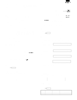
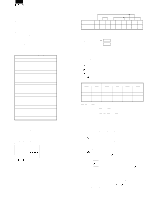
4
-
5
-
6
-
7
-
8
-
9
-
10
-
11
-
12
-
13
-
14
-
15
-
16
-
17
-
18
-
19
-
20
-
21
-
22
-
23
-
24
-
25
-
26
-
27
-
28
-
29
-
30
-
 31
31 -
 32
32 -
 33
33 -
 34
34 -
 35
35 -
 36
36 -
 37
37 -
 38
38 -
 39
39 -
 40
40 -
 41
41 -
42
-
43
-
44
-
45
-
46
-
47
-
48
-
49
-
50
-
51
-
52
-
53
-
54
-
55
-
56
-
57
-
58
-
59
-
60
-
61
-
62
-
63
-
64
-
65
-
66
-
67
-
68
-
69
-
70
-
71
-
72
-
73
-
74
-
75
-
76
 |
 |