Sharp ER-A450T Service Manual - Page 38
Down Load Function
 |
View all Sharp ER-A450T manuals
Add to My Manuals
Save this manual to your list of manuals |
Page 38 highlights
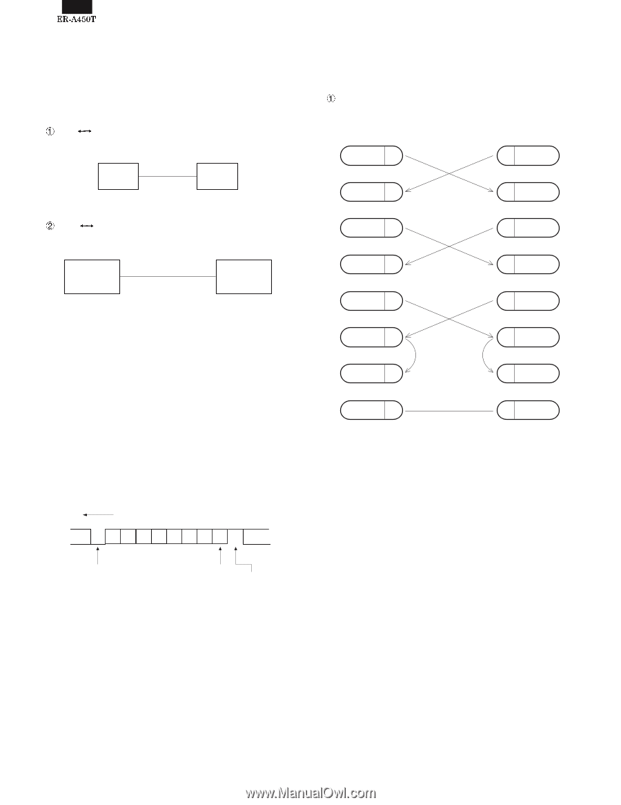
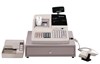
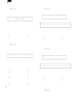
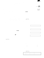
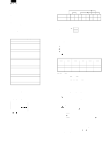
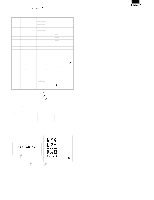
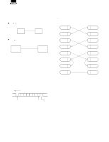
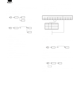
CHAPTER 6. DOWN LOAD FUNCTION 1. General RAM data can be transmitted in the following two methods. Save the data before servicing as follows: ECR ECR • Cable: 9 pin D-SUB - 9 pin D-SUB ECR ECR Fig. 1-1 ECR ER-02FD • Cable: 9 pin D-SUB - 25 pin D-SUB ECR ER-02FD Fig. 1-2 2. SIO interface specification 1) Operation: Simplex 2) Line configuration: Direct connect 3) Data rate: 19200, 9600, 4800, 2400, 1200, 600, 300BPS (Selected by SRV JOB#903-A) 4) Sync mode: Asynchronous 5) Checking: Vertical parity (odd) 6) Code: 7 bits (ASCII) 7) Bit sequence: LSB first 8) Line level: RS232 level 9) Data forma: LSB MSB b1 b2 b3 b4 b5 b6 b7 P Start bit FIg. 2-1 Parity bit Stop bit 3. Location of connector pins ECR-ECR cable 9PIN D-SUB ECR 9PIN D-SUB ECR SD 3 3 SD RD 2 2 RD RTS 7 7 RTS DCD 1 1 DCD DTR 4 4 DTR DSR 6 6 DSR CTS 8 8 CTS SG 5 SD : TRANSMITTED DATA RD : RECEIVED DATA DTR: DATA TERMINAL READY DSR: DATA SET READY RTS: REQUEST TO SEND DCD: DATA CARRIER DETECTOR CTS: CLEAR TO SEND Fig. 3-1 5 SG 6 - 1
-
 1
1 -
2
-
3
-
4
-
5
-
6
-
7
-
8
-
9
-
10
-
11
-
12
-
13
-
14
-
15
-
16
-
17
-
18
-
19
-
20
-
21
-
22
-
23
-
24
-
25
-
26
-
27
-
28
-
29
-
30
-
31
-
32
-
 33
33 -
 34
34 -
 35
35 -
 36
36 -
 37
37 -
 38
38 -
 39
39 -
 40
40 -
 41
41 -
 42
42 -
 43
43 -
44
-
45
-
46
-
47
-
48
-
49
-
50
-
51
-
52
-
53
-
54
-
55
-
56
-
57
-
58
-
59
-
60
-
61
-
62
-
63
-
64
-
65
-
66
-
67
-
68
-
69
-
70
-
71
-
72
-
73
-
74
-
75
-
76
 |
 |