Sharp ER-A450T Service Manual - Page 31
Test Function - er a450
 |
View all Sharp ER-A450T manuals
Add to My Manuals
Save this manual to your list of manuals |
Page 31 highlights
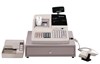
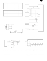
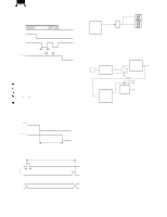
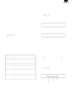
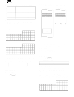
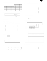
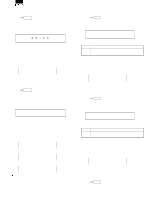
CHAPTER 5. TEST FUNCTION 1. General 1) This diagnostic program has been developed for diagnosing machine functions in the field. The program is contained within the ER-A450S. The diagnostic program is stored in the external ROM which will be executed by the CPU (H8/510) which requires the following diagnostic operations: a) Proper power supply voltages are mandatory for logic circuits (+5V, VDD, POFF, +12.5V, +24V). b) CPU input/output pins, CPU internal logic, CKDC8, MPCA7, system bus and common ROM/RAM must be working properly. 2. Operational procedure To start the diagnostic program, you must enter the following command. SRV mode : XXX CA/AT Test code The key assignment must be properly set and the ROM and RAM must be operating properly to go into this mode. This is necessary because the control jumps to the program area in the SRV mode. A master reset must be performed before operating the ECR for the first time or the ER-03RA is installed. After any other options is installed, a program reset is required. When the master reset or program reset is performed, be sure to check the printout on the journal paper. For Farther details on the MRS procedures, please refer to page 3-1. 3. Test command list With the SRV mode and the following test code entry, the test start. CODE 100 101 102 104 105 106 108 109 110 111 120 130 150 200 501 550 DESCRIPTION Display & Buzzer test Key code & Cashier key test R/J printer test Keyboard test Mode switch test Printer sensor test Calendar osilator test SSP test Drawer open sensor test (For standard drawer) Drawer open sensor test (For remote drawer) Standard RAM test Standard ROM test Printer dot pulse width adjustment Option RAM test RS-232 channel 1 Loop back check RS-232 channel 8 Loop back check 4. Test contents [1] Display & Buzzer test 1) Key operation 100 CA/AT 2) Functional description Displays the following message on the front and the rear display boards. 1. 2. 3. 4. 5. 6. 7. 8. 9. 0. A decimal point shifts from the lower number of digit by one digit (per 200m sec.). Next, the display the following segments (for approx. 1 sec.). 8. 8. 8. 8. 8. 8. 8. 8. 8. 8. The above two kinds of displays repeat continuously. The buzzer sounds continuously during test. 3) Check items a) The display must be correctly shown at each position. b) The luminosity of displays must be uniform and even at each position. c) Abnormal buzzer sound indicate a problem. 4) Test termination Press any key. The test terminates and the test No. and message is printed 1 0 0 [2] Key code & Cashier key test 1) Key operation 101 CA/AT 2) Functional description Key code, MRS switch state and Cashier code are displayed. Key code (Not used) Cashier code 5 - 1
-
 1
1 -
2
-
3
-
4
-
5
-
6
-
7
-
8
-
9
-
10
-
11
-
12
-
13
-
14
-
15
-
16
-
17
-
18
-
19
-
20
-
21
-
22
-
23
-
24
-
25
-
 26
26 -
 27
27 -
 28
28 -
 29
29 -
 30
30 -
 31
31 -
 32
32 -
 33
33 -
 34
34 -
 35
35 -
 36
36 -
37
-
38
-
39
-
40
-
41
-
42
-
43
-
44
-
45
-
46
-
47
-
48
-
49
-
50
-
51
-
52
-
53
-
54
-
55
-
56
-
57
-
58
-
59
-
60
-
61
-
62
-
63
-
64
-
65
-
66
-
67
-
68
-
69
-
70
-
71
-
72
-
73
-
74
-
75
-
76
 |
 |
