Sharp ER-A450T Service Manual - Page 17
Tprc1 F258024pc
 |
View all Sharp ER-A450T manuals
Add to My Manuals
Save this manual to your list of manuals |
Page 17 highlights
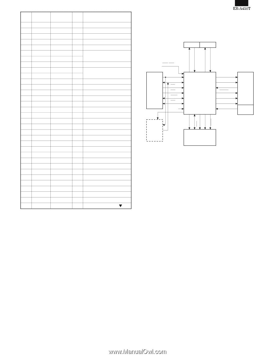
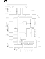
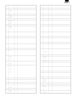
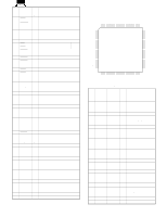
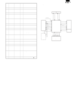
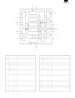
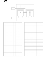
Pin No. SYMBOL SIGNAL NAME IN/ OUT FUNCTION 32 KR6 KR6 IN KEY RETURN 6 33 KR7 KR7 IN KEY RETURN 7 34 AVRF GND 35 AVDD VDD 36 /RESET /RES0 IN 37 XT2 38 XT1 32.768 KHz 39 IC GND 40 X2 41 X1 4.19 MHz 42 VSS1 GND 43 LDRQ LDRQ IN LORD REQUEST 44 ERC ERC IN EVENT READ CANCEL 45 SHEN /SHEN OUT SHIFT ENABLE 46 /RES1 /RESETS OUT SYSTEM TO RESET 47 ST6 ST6 OUT KEY STROBE 6 48 ST7 ST7 OUT KEY STROBE 7 49 ST8 ST8 OUT KEY STROBE 8 50 ST9 NU OUT KEY STROBE 9 51 /POFF /POFF IN POWER OFF 52 BUZ BUZ OUT BUZZER 53 T0 G1 OUT DISPLAY DIGIT 1 54 T1 G2 OUT DISPLAY DIGIT 2 55 T2 G3 OUT DISPLAY DIGIT 3 56 T3 G4 OUT DISPLAY DIGIT 4 57 T4 G5 OUT DISPLAY DIGIT 5 58 T5 G6 OUT DISPLAY DIGIT 6 59 T6 G7 OUT DISPLAY DIGIT 7 60 T7 G8 OUT DISPLAY DIGIT 8 61 T8 G9 OUT DISPLAY DIGIT 9 62 T9 G10 OUT DISPLAY DIGIT 10 63 T10 NU OUT DISPLAY DIGIT 11 64 ID NU OUT DISPLAY SEGMENT 2-4. TPRC1 (F258024PC) 1) General TPRC1 is the LSI circuit of the peripheral circuits of the microcomputer required for thermal printer control. Auto cutter Pulse motor CTAO,CTBO PFP,PCRES XRS,XJS RVPON,JVPON RTRM,PTJM POF,RES CPU (H8/500) A0~23 D0~7 RD WR WAIT INT PHAI CG ROM BD0~2 BA0~15 BRD BWR BRAS (BRAS) TPRC1 SO CLOCK SI LATCH ST1~4 HCD PHUP,PSP, PST,POP Thermal head Switch sensor PB RAM (SRAM) Fig. 2-6 The CPU is designed for use with H8/500. The bus I/F, however, is not restricted to the design concept. The printer is designed mainly for use with PR-58. However, the thermalhead composition (the dot number and the block number) is rather flexible. 1. Auto cutter (Option) 2. Pulse motor 3. Thermalhead 4. Switch 4 - 9
-
 1
1 -
2
-
3
-
4
-
5
-
6
-
7
-
8
-
9
-
10
-
11
-
 12
12 -
 13
13 -
 14
14 -
 15
15 -
 16
16 -
 17
17 -
 18
18 -
 19
19 -
 20
20 -
 21
21 -
 22
22 -
23
-
24
-
25
-
26
-
27
-
28
-
29
-
30
-
31
-
32
-
33
-
34
-
35
-
36
-
37
-
38
-
39
-
40
-
41
-
42
-
43
-
44
-
45
-
46
-
47
-
48
-
49
-
50
-
51
-
52
-
53
-
54
-
55
-
56
-
57
-
58
-
59
-
60
-
61
-
62
-
63
-
64
-
65
-
66
-
67
-
68
-
69
-
70
-
71
-
72
-
73
-
74
-
75
-
76
 |
 |