Sharp ER-A450T Service Manual - Page 5
RS232 Interface
 |
View all Sharp ER-A450T manuals
Add to My Manuals
Save this manual to your list of manuals |
Page 5 highlights
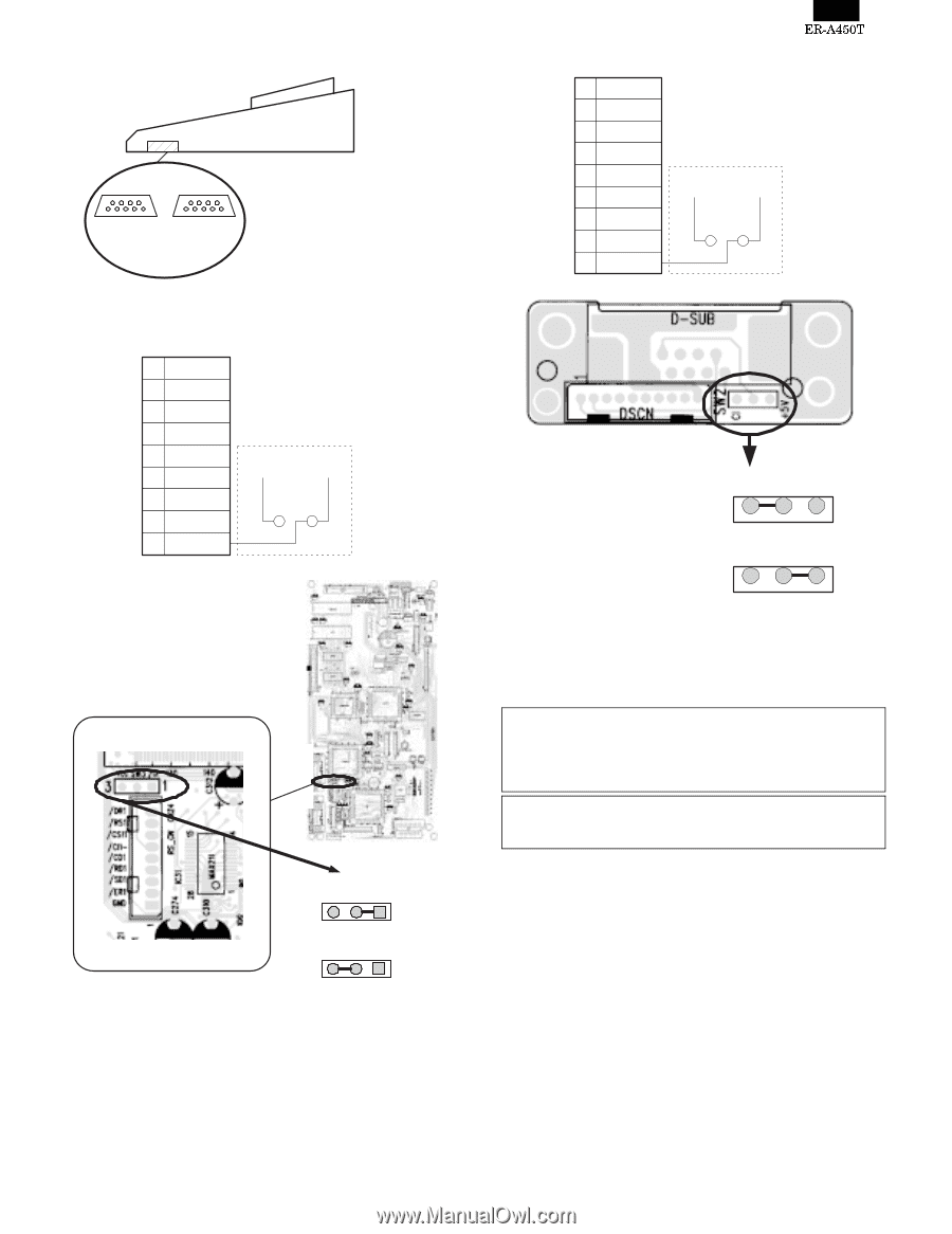
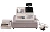
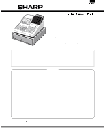
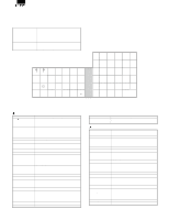
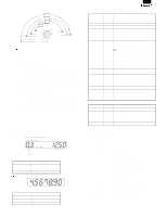
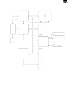
7. RS232 Interface Channel No.: Port 1(CH8) Channel No.: Port 2(CH1) 1) Port 2 (CH1) 1 /CD 2 RD 3 SD 4 /ER 5 GND 6 /DR 7 /RS 8 /CS 9 on the Main PWB VCC /CI SW3 2) Port 1 (CH8) 1 /CD 2 RD 3 SD 4 /ER 5 GND 6 /DR 7 /RS 8 /CS 9 on the RS connector PWB +5V /CI SW2 +5V SW2 CI Pin No.9 : /CI signal (Default) Pin No.9 : +5V signal +5V SW2 CI Pin No.9 : /CI signal (Default) VCC SW3 /CI 3 1 Pin No.9 : Vcc(+5V) signal VCC SW3 /CI 3 1 The No.9 pin signal of the Port 1 (CH8) can be selected between the /CI signal and the +5V signal by changing the connection of the SW2 (initial value: /CI signal) NOTE: Optional bar code reader: When connecting an ER-A6HS1, connect it to the Port 1 (or 2) and switch the No.9 pin signal to the +5V signal. When connecting other RS232 devices to either the Port 1 (or 2), make sure the No.9 pin signal is proper before connecting the device. If you want to connect an RS232 device to the ECR with the No.9 pin of the port 1 (or 2) set to +5V, make sure the AC cable of the ECR is disconnected from the wall outlet to protect the device. 1 - 4
-
 1
1 -
 2
2 -
 3
3 -
 4
4 -
 5
5 -
 6
6 -
 7
7 -
 8
8 -
 9
9 -
 10
10 -
 11
11 -
12
-
13
-
14
-
15
-
16
-
17
-
18
-
19
-
20
-
21
-
22
-
23
-
24
-
25
-
26
-
27
-
28
-
29
-
30
-
31
-
32
-
33
-
34
-
35
-
36
-
37
-
38
-
39
-
40
-
41
-
42
-
43
-
44
-
45
-
46
-
47
-
48
-
49
-
50
-
51
-
52
-
53
-
54
-
55
-
56
-
57
-
58
-
59
-
60
-
61
-
62
-
63
-
64
-
65
-
66
-
67
-
68
-
69
-
70
-
71
-
72
-
73
-
74
-
75
-
76
 |
 |