Sharp FO-2970M Service Manual - Page 2

] Circuit description of TEL/LIU and Hook SW PWB - manual

Page 2 highlights

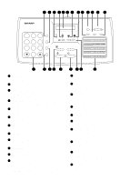
FO-2970MU CONTENTS CHAPTER 1. GENERAL DESCRIPTION [1] Specifications 1-1 [2] Operation panel 1-2 [3] Refer to the service manual of FO-2950MU [4] Refer to the service manual of FO-2950MU [5] Refer to the service manual of FO-2950MU [6] Refer to the service manual of FO-2950MU [7] Refer to the service manual of FO-2950MU CHAPTER 2. ADJUSTMENTS [1] Adjustments 2-1 [2] Diagnostics and service soft switches 2-4 [3] Troubleshooting 2-27 [4] Error code table 2-28 CHAPTER 3. MECHANICAL DESCRIPTION [1] Refer to the service manual of FO-2950MU [2] Refer to the service manual of FO-2950MU CHAPTER 4. DIAGRAMS [1] Block diagram 4-1 [2] Wiring diagram 4-2 [3] Point-to-point diagram and connector signal name 4-3 CHAPTER 5. CIRCUIT DESCRIPTION [1] Circuit description 5-1 [2] Circuit description of control PWB 5-2 [3] Circuit description of TEL/LIU and Hook SW PWB 5-21 [4] Circuit description of power supply PWB 5-23 [5] Circuit description of CIS UNIT 5-24 CHAPTER 6. CIRCUIT SCHEMATICS AND PARTS LAYOUT [1] Control PWB circuit 6-1 [2] TEL/LIU and Hook SW PWB circuit 6-12 [3] Printer PWB circuit 6-15 [4] Power supply PWB circuit 6-18 [5] Operation panel PWB circuit 6-20 CHAPTER 7. OPERATION FLOWCHART [1] Refer to the service manual of FO-2950MU [2] Refer to the service manual of FO-2950MU CHAPTER 8. OTHERS [1] Refer to the service manual of FO-2950MU [2] Refer to the service manual of FO-2950MU PARTS GUIDE

  • 1
  • 2
  • 3
  • 4
  • 5
  • 6
  • 7
  • 8
  • 9
  • 10
  • 11
  • 12
  • 13
  • 14
  • 15
  • 16
  • 17
  • 18
  • 19
  • 20
  • 21
  • 22
  • 23
  • 24
  • 25
  • 26
  • 27
  • 28
  • 29
  • 30
  • 31
  • 32
  • 33
  • 34
  • 35
  • 36
  • 37
  • 38
  • 39
  • 40
  • 41
  • 42
  • 43
  • 44
  • 45
  • 46
  • 47
  • 48
  • 49
  • 50
  • 51
  • 52
  • 53
  • 54
  • 55
  • 56
  • 57
  • 58
  • 59
  • 60
  • 61
  • 62
  • 63
  • 64
  • 65
  • 66
  • 67
  • 68
  • 69
  • 70
  • 71
  • 72
  • 73
  • 74
  • 75
  • 76
  • 77
  • 78
  • 79
  • 80
  • 81
  • 82
  • 83
  • 84
  • 85
  • 86
  • 87
  • 88
  • 89
  • 90
  • 91
  • 92
  • 93
  • 94
  • 95
  • 96
  • 97
  • 98
  • 99
  • 100
  • 101
  • 102
  • 103
  • 104
  • 105
  • 106
  • 107
  • 108
  • 109
  • 110
  • 111
  • 112
  • 113
  • 114

FO-2970MU
CONTENTS
CHAPTER 1. GENERAL DESCRIPTION
[1] Specifications . . . . . . . . . . . . . . . . . . . . . . . . . . . . . . . . . . . . . . . . . . . . . . . . . . . . . . . . . . . . . . . . . .
1-1
[2] Operation panel
. . . . . . . . . . . . . . . . . . . . . . . . . . . . . . . . . . . . . . . . . . . . . . . . . . . . . . . . . . . . . . . .
1-2
[3] Refer to the service manual of FO-2950MU
[4] Refer to the service manual of FO-2950MU
[5] Refer to the service manual of FO-2950MU
[6] Refer to the service manual of FO-2950MU
[7] Refer to the service manual of FO-2950MU
CHAPTER 2. ADJUSTMENTS
[1] Adjustments
. . . . . . . . . . . . . . . . . . . . . . . . . . . . . . . . . . . . . . . . . . . . . . . . . . . . . . . . . . . . . . . . . . .
2-1
[2] Diagnostics and service soft switches
. . . . . . . . . . . . . . . . . . . . . . . . . . . . . . . . . . . . . . . . . . . . . . .
2-4
[3] Troubleshooting
. . . . . . . . . . . . . . . . . . . . . . . . . . . . . . . . . . . . . . . . . . . . . . . . . . . . . . . . . . . . . . .
2-27
[4] Error code table
. . . . . . . . . . . . . . . . . . . . . . . . . . . . . . . . . . . . . . . . . . . . . . . . . . . . . . . . . . . . . . .
2-28
CHAPTER 3. MECHANICAL DESCRIPTION
[1] Refer to the service manual of FO-2950MU
[2] Refer to the service manual of FO-2950MU
CHAPTER 4. DIAGRAMS
[1] Block diagram
. . . . . . . . . . . . . . . . . . . . . . . . . . . . . . . . . . . . . . . . . . . . . . . . . . . . . . . . . . . . . . . . .
4-1
[2] Wiring diagram . . . . . . . . . . . . . . . . . . . . . . . . . . . . . . . . . . . . . . . . . . . . . . . . . . . . . . . . . . . . . . . . .
4-2
[3] Point-to-point diagram and connector signal name
. . . . . . . . . . . . . . . . . . . . . . . . . . . . . . . . . . . . .
4-3
CHAPTER 5. CIRCUIT DESCRIPTION
[1] Circuit description . . . . . . . . . . . . . . . . . . . . . . . . . . . . . . . . . . . . . . . . . . . . . . . . . . . . . . . . . . . . . . .
5-1
[2] Circuit description of control PWB
. . . . . . . . . . . . . . . . . . . . . . . . . . . . . . . . . . . . . . . . . . . . . . . . . .
5-2
[3] Circuit description of TEL/LIU and Hook SW PWB
. . . . . . . . . . . . . . . . . . . . . . . . . . . . . . . . . . . .
5-21
[4] Circuit description of power supply PWB . . . . . . . . . . . . . . . . . . . . . . . . . . . . . . . . . . . . . . . . . . . .
5-23
[5] Circuit description of CIS UNIT
. . . . . . . . . . . . . . . . . . . . . . . . . . . . . . . . . . . . . . . . . . . . . . . . . . .
5-24
CHAPTER 6. CIRCUIT SCHEMATICS AND PARTS LAYOUT
[1] Control PWB circuit
. . . . . . . . . . . . . . . . . . . . . . . . . . . . . . . . . . . . . . . . . . . . . . . . . . . . . . . . . . . . .
6-1
[2] TEL/LIU and Hook SW PWB circuit . . . . . . . . . . . . . . . . . . . . . . . . . . . . . . . . . . . . . . . . . . . . . . . .
6-12
[3] Printer PWB circuit . . . . . . . . . . . . . . . . . . . . . . . . . . . . . . . . . . . . . . . . . . . . . . . . . . . . . . . . . . . . .
6-15
[4] Power supply PWB circuit
. . . . . . . . . . . . . . . . . . . . . . . . . . . . . . . . . . . . . . . . . . . . . . . . . . . . . . .
6-18
[5] Operation panel PWB circuit
. . . . . . . . . . . . . . . . . . . . . . . . . . . . . . . . . . . . . . . . . . . . . . . . . . . . .
6-20
CHAPTER 7. OPERATION FLOWCHART
[1] Refer to the service manual of FO-2950MU
[2] Refer to the service manual of FO-2950MU
CHAPTER 8. OTHERS
[1] Refer to the service manual of FO-2950MU
[2] Refer to the service manual of FO-2950MU
PARTS GUIDE