Sharp FO-2970M Service Manual - Page 5
Adjustments
 |
View all Sharp FO-2970M manuals
Add to My Manuals
Save this manual to your list of manuals |
Page 5 highlights
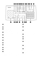
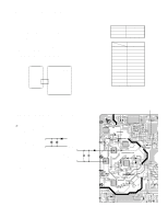
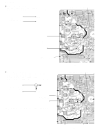
CHAPTER 2. ADJUSTMENTS [1] Adjustments General Since the following adjustments and settings are provided for this model, make adjustments and/or setup as necessary. 1. Adjustments Adjustments of output voltage (FACTORY ONLY) 1. Install the power supply unit in the machine. 2. Set the recording paper and document. 3. When the document is loaded, power is supplied to the output lines. Confirm that outputs are within the limits below. Output voltage settings Power Supply PWB 1 CN101 12 Printer PWB 1 CNPW 12 Fig. 1 2. High voltage power adjustments The high voltage power adjustments are composed of the MC output voltage adjustment and the DC bias output voltage adjustment. Either adjustment is performed with the diag function. (MAIN CHG ADJUST MODE) 1 MC output voltage adjustment In the measurement circuit shown below, adjust VR1 to be -1050V ~ -1200V (aim at -1100V) Measure with the high voltage tester (effective value meter). MC DRUM + MC output voltage check - • Capacitor: 1000pF/3KV (VCKYQY3FB102K) • Diode: SHV-03 (VHDSHV03///-1) FO-2970MU Output +5V +24VH +24V* Voltage limits 4.75V~5.25V 23.04V~24.96V 23.04V~24.96V Connector PIN No. No. CNPW 1 +5V 2 DG 3 DG 4 +24VH 5 MG 6 MG 7 +24VS 8 PWRLY- 9 HLON- 10 +24V 11 +24V 12 ZC VR1 (MC output voltage adjustment volume) 2 - 1 Fig. 3 Fig.2
-
 1
1 -
 2
2 -
 3
3 -
 4
4 -
 5
5 -
 6
6 -
 7
7 -
 8
8 -
 9
9 -
 10
10 -
 11
11 -
12
-
13
-
14
-
15
-
16
-
17
-
18
-
19
-
20
-
21
-
22
-
23
-
24
-
25
-
26
-
27
-
28
-
29
-
30
-
31
-
32
-
33
-
34
-
35
-
36
-
37
-
38
-
39
-
40
-
41
-
42
-
43
-
44
-
45
-
46
-
47
-
48
-
49
-
50
-
51
-
52
-
53
-
54
-
55
-
56
-
57
-
58
-
59
-
60
-
61
-
62
-
63
-
64
-
65
-
66
-
67
-
68
-
69
-
70
-
71
-
72
-
73
-
74
-
75
-
76
-
77
-
78
-
79
-
80
-
81
-
82
-
83
-
84
-
85
-
86
-
87
-
88
-
89
-
90
-
91
-
92
-
93
-
94
-
95
-
96
-
97
-
98
-
99
-
100
-
101
-
102
-
103
-
104
-
105
-
106
-
107
-
108
-
109
-
110
-
111
-
112
-
113
-
114
 |
 |
