Sharp FO-2970M Service Manual - Page 7
FO-2970MU, Control PWB Bottom side
 |
View all Sharp FO-2970M manuals
Add to My Manuals
Save this manual to your list of manuals |
Page 7 highlights
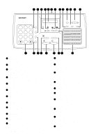
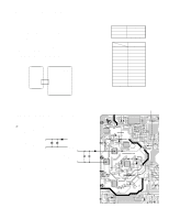
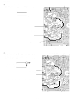
3. IC protectors replacement ICPs (IC Protectors) are installed to protect the TX motor drive circuit and verification stamp drive circuit. ICPs protect various ICs and electronic circuits from an overcurrent condition. The location of ICPs are shown below: (1) F100 (ICPS10) is installed in order to protect IC's from and overcurrent generated in the verification stamp drive circuit. If F100 is open, replace it with a new one. 4. Settings (1) Dial mode selector OPTION SETTING: DIAL MODE (Soft Switch No. SW2 DATA No. 1) Use this to set the fax machine to the type of telephone line you are on. • The factory setting is "TONE". (step 1) Select "OPTION SETTING". KEY: FUNCTION 4 DISPLAY: OPTION SETTING PRESS or # (step 2) Select "DIAL MODE". KEY: Push # until " DIAL MODE " is indicated because the number of # s changes by the models. DISPLAY: DIAL MODE 1= TONE, 2= PULSE (step 3) Select, using "1" or "2". KEY: 1 DISPLAY: TONE SELECTED KEY: 2 DISPLAY: PULSE SELECTED (step 4) End, using the "STOP" key. KEY: STOP FO-2970MU CNRTH CNFUSE F100 CNMT IC6 CNPRT CNPN CNCIS CNLIUA CNSP CNLIUB Control PWB (Bottom side) Fig.5 2 - 3
-
 1
1 -
 2
2 -
 3
3 -
 4
4 -
 5
5 -
 6
6 -
 7
7 -
 8
8 -
 9
9 -
 10
10 -
 11
11 -
 12
12 -
13
-
14
-
15
-
16
-
17
-
18
-
19
-
20
-
21
-
22
-
23
-
24
-
25
-
26
-
27
-
28
-
29
-
30
-
31
-
32
-
33
-
34
-
35
-
36
-
37
-
38
-
39
-
40
-
41
-
42
-
43
-
44
-
45
-
46
-
47
-
48
-
49
-
50
-
51
-
52
-
53
-
54
-
55
-
56
-
57
-
58
-
59
-
60
-
61
-
62
-
63
-
64
-
65
-
66
-
67
-
68
-
69
-
70
-
71
-
72
-
73
-
74
-
75
-
76
-
77
-
78
-
79
-
80
-
81
-
82
-
83
-
84
-
85
-
86
-
87
-
88
-
89
-
90
-
91
-
92
-
93
-
94
-
95
-
96
-
97
-
98
-
99
-
100
-
101
-
102
-
103
-
104
-
105
-
106
-
107
-
108
-
109
-
110
-
111
-
112
-
113
-
114
 |
 |
