Sharp GX20 Service Manual
Sharp GX20 Manual
 |
View all Sharp GX20 manuals
Add to My Manuals
Save this manual to your list of manuals |
Sharp GX20 manual content summary:
- Sharp GX20 | Service Manual - Page 1
of used batteries according to the instruction. CONTENTS CHAPTER 1. GENERAL DESCRIPTION [1] Specifications 1-1 [2] Names of parts 1-2 [3] Operation manual 1-3 CHAPTER 2. ADJUSTMENTS [1] Adjustments SHARP Program Support Tool (SPST)........ 2-1 [2] SHARP RF Test tool manual 2-30 [3] Adjustment - Sharp GX20 | Service Manual - Page 2
Sound: Mobile light: External DC supply voltage: Battery: Standby time: Talk time: Others: 16-polyphonic ring melodies 7 colours 5.2 V 3.7 V, 720 mAh, Li-Ion 100 ~ 250 hours 180 ~ 240 min. Side key Infrared port 1.2 L/P (maximum distance 20 cm) Connector for AC charger and data cable Standard hands - Sharp GX20 | Service Manual - Page 3
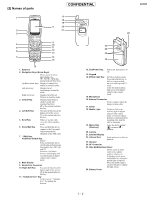
16. External Connector: Used to connect either the charger or data cable. 17. Aerial 18. Mobile Light: Used as a flash or an auxiliary light in digital camera/video camera mode, as a battery charge indicator, or notification for incoming calls, data/fax calls or messages. 19. Macro Dial: (Close - Sharp GX20 | Service Manual - Page 4
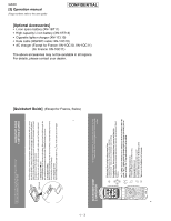
GX20 [3] Operation manual (Page numbers refer to the user guide) [Optional Accessories] • Li-ion spare battery (XN-1BT11) • High capacity Li-ion battery (XN-1BT13) • Cigarette lighter charger (XN-1CL10) • Data cable (RS232C cable: XN-1DC10) • AC charger (Except for France: XN-1QC10, XN-1QC11) (for - Sharp GX20 | Service Manual - Page 5
only pay for data you send or get, not how long you're connected. Or link directly to Vodafone live! services: In the main Menu, select the Vodafone live! section, and choose your service: Games: Online fun and games to download... Ringtones: Download music, sounds and ringtones. Pictures: Download - Sharp GX20 | Service Manual - Page 6
. Choose an image and follow the instructions to download it. Then go to Settings (in the main Menu)/Phone Settings/Main Display/Wallpaper/My Pictures, and select your downloaded image. 3. Download new games: To add more arcade quality games to your handset, go to Fun & Games (in the main Menu) and - Sharp GX20 | Service Manual - Page 7
Data cable • Full charged battery • RF test instrument: CMU200 • GPIB interface: National Instruments USB-GPIB cable Model No.: NI GPIB-USB-B • The battery should be fully charged. 3. Introduction 3.1. Functions SPST offers five key functions: 1. Software download 2. User data - Sharp GX20 | Service Manual - Page 8
3.3.1 Identification SPST downloads and displays the main data configured in GX20. 1) On the SPST startup screen, press "Identity". Figure 3 2) Connect PC and MS with a Data cable. 3) Remove the SIM card and turn on the phone. → Regular display. 4) Select the COM port. 5) Press - Sharp GX20 | Service Manual - Page 9
Press "OK" when **** appears on the GX20 display. 9) Make sure "Success!!" appears. Check the data and exit. Figure 5 Attachment 1 Operator Code Chart No. 01 02 03 04 05 06 Paid Refer to the attachment 1 for the operator code. Figure 6 Software version: 012 IMEISV: 06 Country UK Spain France - Sharp GX20 | Service Manual - Page 10
GX20 CONFIDENTIAL 3.3.2 User data transfer SPST saves and downloads all the following user data. 1) Connect PC and MS with a Data cable and turn on MS. 2) Activate the software. Figure 7 a) Select the COM port. You cannot specify the communication protocol. (115 kbps) b) Press "Recognition". Do - Sharp GX20 | Service Manual - Page 11
CONFIDENTIAL 4) If "BACKUP" is pressed, the dialog box for file selection appears. Select the file and press "Save". GX20 The buttons are grayed out during the process. Figure 9 Firue 10 2 - 5 - Sharp GX20 | Service Manual - Page 12
GX20 CONFIDENTIAL When they return to black, the process is complete. Press "END" to exit. Figure 11 5) If "RESTORE" is pressed, the following confirmation dialog box - Sharp GX20 | Service Manual - Page 13
. GX20 Figure 14 3.3.3 Default setting You can reset settings to the factory default. The following will be performed: 1. All user data in some countries and remains disabled. Check the country code.) 1) Connect the cable to the phone. 2) Press the power button to enter the standby - Sharp GX20 | Service Manual - Page 14
35 seconds for initialization. Figure 17 5) When MEPLOCK data exists, the screen below appears asking if the data should be restored. If there is no data, the screen in 8) appears. Figure 18 6) Select [Yes]. After the following screen, turn on the phone power and click the [Retry] button. To cancel - Sharp GX20 | Service Manual - Page 15
after initialization and the phone turns off. Figure 20 8) Click the [OK] button. After the following screen, disconnect the cable. GX20 The setting is completed. 3.3.4 RF Adjustment Tool 1) Tool layout MS Figure 21 GSM tester Data cable GPIB cable PC Figure 22 2 - 9 Cable loss should be - Sharp GX20 | Service Manual - Page 16
GX20 CONFIDENTIAL 2) Preparation • Connect PC and GSM tester with a GPIB cable. • Connect PC and MS with a Data cable. (Use a full charged battery or one close.) • Connect an antenna input/output cable of GSM tester to MS. 3) Default setting for the program. • Activate the program and set - Sharp GX20 | Service Manual - Page 17
4) RF adjustment 1. Press "Calibration". 2. When initialization is complete, press "OK". CONFIDENTIAL 3. Turn on the phone and press "OK". Figure 24 Figure 25 4. Make sure the phone is turned on and press "OK". (Adjustments start.) 5. Press "OK". 6. The startup screen appears. Figure 26 Figure - Sharp GX20 | Service Manual - Page 18
GX20 5) RF performance check Press "Check". 1. When initialization is complete, press "OK". CONFIDENTIAL 2. Turn on the phone, enter the PIN code and press "OK". Figure 28 3. Make sure that the phone is in the idle mode and press "OK". Figure 29 4. Press the keys 1, 2, 3 and Send and press "OK - Sharp GX20 | Service Manual - Page 19
" and press "OK". Figure 34 8. RF performance check is complete. Press "Save As..."and name the file to save the result. Press "OK" to exit. GX20 The following will be displayed in case of failure. Figure 35 9. Press "OK". 10.The startup screen appears. Figure 36 Figure 37 2 - 13 - Sharp GX20 | Service Manual - Page 20
GX20 Attachment 2 Whole inspection list by RF performance check. Band Send- No. Item Mod_spectrum -800 16 Mod_spectrum -600 17 Mod_spectrum -400 18 Mod_spectrum -250 19 Mod_spectrum -200 20 Mod_spectrum +200 21 Mod_spectrum +250 22 Mod_spectrum +400 23 Mod_spectrum +600 24 Mod_spectrum +800 - Sharp GX20 | Service Manual - Page 21
error (RMS) Phase error (RMS) Phase error (Peak) Phase error (Peak) Phase error (Peak) Mod_spectrum -800 Mod_spectrum -600 Mod_spectrum -400 Mod_spectrum -250 GX20 Channel PCL 699CH 699CH 512CH 512CH 512CH 512CH 512CH 512CH 512CH 512CH 855CH 855CH 855CH 855CH 855CH 855CH 855CH 855CH 699CH 699CH - Sharp GX20 | Service Manual - Page 22
GX20 Band Send- No. Item to be inspected ing/ Recei ve 247 Mod_spectrum -200 PCL0 PCL5 PCL15 PCL0 PCL0 PCL0 PCL0 PCL0 Troubleshooting list according to the results of RF performance check. Test item Check parts for GSM Check parts for DCS Check parts for PCS Tx Sending output IC831, IC881, - Sharp GX20 | Service Manual - Page 23
length: 8 bit Parity bit: None Stop bit length: 1 bit Operating environment for the loading loader Phone: GX20 Communication mode: Asynchronous mode Data length: 8 bit Parity bit: None Stop bit length: 1 bit 1) Description of the screens. 1) Activation You can start the application either from - Sharp GX20 | Service Manual - Page 24
battery and remove the check from "Communication Box" if using a Data cable for the downloading operation. • Start downloading after the phone has been properly turned off in order to clear the Backup RAM. • If you select "FileSystem Initialize" for the download, user's data stored in the phone - Sharp GX20 | Service Manual - Page 25
1) Selecting a file. Press "Select File" button to open the dialog. Select a file you wish to download. You can only select the file with Motorola format. GX20 Figure 39 The dialog screen to select the file 2) Selecting a COM Port. Select the COM Port that connects the PC and the - Sharp GX20 | Service Manual - Page 26
is used for the handshaking between the PC and the phone. Make sure that cable is properly connected to the phone while the handshaking if using "Communication Box Ver. 2G". Switch on the power buttons from No.10 to No.1 when "Sending Sync Byte.../Press Power Button" message appears. You may turn on - Sharp GX20 | Service Manual - Page 27
CONFIDENTIAL GX20 4) Starting the download. Press [Start Loading Flash] button after you finish 42 [Using a Data cable] If using a Data cable for the downloading operation, press Power button of the phone after [Please remove AC charger, when you use PCcableSending Sync Byte.../Press Power Button - Sharp GX20 | Service Manual - Page 28
Data cable:] 1. Make sure to remove the AC charger from the Data cable. Otherwise it may cause the charging application to be activated and downloading operation cannot be operated properly. 2. Use a fully charged battery No.1 when "Sending Sync Byte.../Press Power user's data stored in the phone - Sharp GX20 | Service Manual - Page 29
CONFIDENTIAL GX20 2) Table of the Loading loader error messags (on the phone side) No. 1 2 3 4 5 6 7 8 9 10 11 12 13 14 15 16 17 18 19 20 21 22 23 while verifying the erase. Indicates that error occurred while writing data. Indicates the Flash address where the error occurred. Indicates the - Sharp GX20 | Service Manual - Page 30
GX20 4) Installation / Un-installation 1) Installation Execute "setup.exe" and activate the setup wizard. CONFIDENTIAL Select a folder you wish to install to. Figure 44 Figure 45 2 - 24 - Sharp GX20 | Service Manual - Page 31
The confirmation screen appears. Select [Next]. CONFIDENTIAL GX20 The Up Grading Tool is being installed. Figure 46 Figure 47 2 - 25 - Sharp GX20 | Service Manual - Page 32
Figure 48 The icon of the Up Grading Tool as shown below is configured on your desktop. You can also activate this application selecting "The GX20 Up Ggrading Tool" from Start menu. Figure 49 The icon of theUp Grading Tool icon 2) Un-installation Execute "setup.exe" and activate the setup wizard - Sharp GX20 | Service Manual - Page 33
The preloaded program is being un-installed. CONFIDENTIAL GX20 The un-installation is complete. Figure 51 Figure 52 2 - 27 - Sharp GX20 | Service Manual - Page 34
GX20 this case, please restart your operation system according to the instruction. Even if such massages do not appear, restart your operation 3 Reset Tool for the phone code Reset the phone code to "0000". 1) Connect the Reset tool to the cable. 2) Execute "PWDinit.exe - Sharp GX20 | Service Manual - Page 35
CONFIDENTIAL 6) Press "Reset". The following confirmation message appears. 7) Press "Yes" . Figure 56 Figure 57 8) When initialization is complete, the dialog box below appears. Press "OK" to turn off the phone. Figure 58 GX20 2 - 29 - Sharp GX20 | Service Manual - Page 36
GX20 [2] SHARP RF Test tool manual 1. Requirements • PC with COM port • Mouse • GX20 Data Cable • PWB repair jig Connect PC and GX20 with Data Cable. 3. Turn on the phone. 4. Start RF Test Tool. 5. Select a COM port to which Data Cable is connected. 6. Press the "Initialize & Read Data" Button. 7. - Sharp GX20 | Service Manual - Page 37
PWB Hook CONFIDENTIAL Setting Pin Hook Setting Pin Hook Setting Pin Figure 62 PWB installation GX20 Black Red PC Data Cable Figure 63 Connections 2 - 31 - Sharp GX20 | Service Manual - Page 38
GX20 CONFIDENTIAL Points Figure 64 Contact points Push Figure 65 Turning power on 2 - 32 - Sharp GX20 | Service Manual - Page 39
band and a channel to test. Settings are applied to all tests. Band selection GX20 Input box [Procedure] 1. Select a band. (GSM, DCS or PCS) 2. Level) using PCL bar. 3. Select Data pattern. 4. Click TX ON to start burst transmission. (You can check each part in this state.) 5. Click TX OFF - Sharp GX20 | Service Manual - Page 40
GX20 CONFIDENTIAL GX20 9 10 11 12 13 14 15 3.3. RX test The phone receives burst signals in this test. TX Power [dBm] 28.6 27.0 26.0 24.0 22.0 20.0 18.0 16.0 14.0 12.0 10.0 8.0 6.0 burst signals in the specified channel. (You can check each part in this state.) 6. Click RX OFF to end receiving - Sharp GX20 | Service Manual - Page 41
GX20 Estimated Power Input box (Integer only) Measured power box Measure button Figure 69 [Procedure] 1. Connect the phone and GSM tester (or Signal Generator) with RF cable than 2dB. 4. Termination Turn off the phone to ensure proper operations. 5. Trouble imfomation When switching DCS and PCS, - Sharp GX20 | Service Manual - Page 42
5. White defect contrast adjustment correction 1. Adjustment procedures of camera temperature 1. Place a thermometer near the unit to be adjusted. Make sure the room temperature is over 0°C. 2. Attach the battery pack and then connect the Data cable. 3. Access the normal mode by holding down the - Sharp GX20 | Service Manual - Page 43
twice. The corrected value is registered. 7. Press the "End/Power" key to exit this mode. 4. External display contrast adjustment 1. Attach the battery pack and then connect the Data cable. 2. Hold down the "End/Power" key for startup in the normal mode. 3. Send the [AT+XDIAG] command to receive the - Sharp GX20 | Service Manual - Page 44
CONFIDENTIAL 1. Attach the battery pack and then connect the Data cable. 2. Access the normal mode by holding down the "End/Power" key. 3. Send the [AT+XDIAG] command to receive the response [DIAGREADY]. 4. "Function Mode *GX20*"is shown on the display. 5. Cover the camera front to block off - Sharp GX20 | Service Manual - Page 45
TP171 TP213 TP109 TP138 TP430 TP421 TP425 TP141 TP418 TP216 GX20 TP177 TP419 TP111 TP110 TP212 TP215 TP217 TP413 TP410 TP211 TP425 TP426 TP428 TP429 TP430 Signal name Power supply for camera (+13V) Power supply for camera (-7V) 13MHzCLK CAMCLK Terminal for LCDC adhesion check 1 Terminal - Sharp GX20 | Service Manual - Page 46
GX20 KEY PWB-B (FRONT SIDE) CONFIDENTIAL TP344 TP308 TP323 TP322 Figure 73 TEST POINT TP No. TP308 TP344 Signal name VEXT_CN DGND 2 - 40 - Sharp GX20 | Service Manual - Page 47
KEY PWB-B (REAR SIDE) TP321 TP348 TP328 TP330 CONFIDENTIAL TP329 TP309 TP313 GX20 TP301 TP345 TP346 TP311 TP315 TP314 TP307 TP305 TP306 TPB334 TP347 TPB332 TPB331 TPB333 TPB336 TPB335 TP317 TP319 TP324 TP320 Figure 74 TEST POINT TP - Sharp GX20 | Service Manual - Page 48
GX20 [5] Troubleshooting 1. Power does not turn on. Connect a battery with voltage of more than 4.0 V. CONFIDENTIAL NOTE: If the cause is damage to 4-level memory (IC106), ensure to upload flash data before operation as initializing user area may prevent detecting the damaged data. Manual test - Sharp GX20 | Service Manual - Page 49
A (From page 2-42) CONFIDENTIAL GX20 More than 3.6 V output at BATT terminal (TPB336)? YES Voltage of below 1.6 V battery (CN303) terminal, or bad soldering. NO Battery or battery mounting defective. NO Blowout of fuse (FS301). NO • Relay FPC_A or connector CN201 defective. • Parts - Sharp GX20 | Service Manual - Page 50
GX20 2. Incoming audio cannot be heard. Phone CONFIDENTIAL Signal output at the Back light FPC earpiece V applied to TP106? NO Voltage of more than 2.4 V applied to Q101 3 pin? YES Parts of hands free connector JK301 3 pin to TP106 defective or connection of Relay FPC_B with CN306 and CN202 - Sharp GX20 | Service Manual - Page 51
Signal output at IC101 5 pin? NO Voltage of 3 V applied to IC101 6 pin? YES CONFIDENTIAL YES Hands free kit defective. GX20 YES JK301 defective or defective connection. YES Parts of hands free connector JK301 4 pin to IC101 5 pin defective or connection of Relay FPC_B with CN306 and CN202 - Sharp GX20 | Service Manual - Page 52
to "Hands free kit" in Troubleshooting "Incoming audio cannot be heard" (see page 2-45). Refer to Troubleshooting, "Charging impossible" (see page defective. NO Hands free car kit defective. Or defective parts of IC302 12 pin to IC104 20 pin and IC104 defective. NO R104 or IC104 defective - Sharp GX20 | Service Manual - Page 53
B (From page 2-46) CONFIDENTIAL GX20 Voltage of approx. 1 V applied to IC102 54 pin? NO Voltage of approx. 1 V applied to IC102 64 pin? NO Voltage of more than 2.4 V applied to Q101 3 pin? YES Parts of R110, R111, C126 and jumper (IC102 64 pin to R111) defective or soldering defective. C Voltage - Sharp GX20 | Service Manual - Page 54
GX20 Hands free kit (Headset) When replacing the hands free kit, output avilable? NO Voltage approx. 1 V applied to IC102 40 pin? NO Voltage of more than 2.4 V applied to Q101 3 pin? YES Parts of R107, R108, C113 and L106 defective or soldering defective. F Voltage of 0 V applied to C186 (IC102 6 pin - Sharp GX20 | Service Manual - Page 55
free car kit defective. GX20 NO Calling available in the Kit" in Troubleshooting "Incoming audio cannot be heard" (see page 2-46). NO Parts of CN302 battery charger. Check that the battery voltage is more than 4.15 V. Does "Red of mobile light (LED405)" turn on/off when press "1" key by manual - Sharp GX20 | Service Manual - Page 56
GX20 5. Vibrator does not operate. CONFIDENTIAL Vibrator terminals contacting the land? NO Dirt or foreign matter detedted at vibrator terminals and the land? Check the vibrator during operation. Vibrator deformed. (Remove foreign matter or replace parts.) YES 3 V square waves output - Sharp GX20 | Service Manual - Page 57
the ring tone volume is set to "Silent", Voice Memo is not played back. Do speaker terminals contact with the land? NO Speaker defective. GX20 YES Resistance of 8 ohms available between the speaker terminals? YES Signal output at the speaker land on the Relay FPC_A? NO Speaker defective. YES - Sharp GX20 | Service Manual - Page 58
GX20 CONFIDENTIAL 8. Movie, Voice Memo cannot be played back. Speaker Key pad tones and incoming-call ring tones normally ? NO Refer to Troubleshooting the capacity bar changed? YES Ringer Volume set to "Silent"? NO YES Parts of IC102 63 pin to IC103 14, 13 pin defective or solder- ing - Sharp GX20 | Service Manual - Page 59
9. Back light does not turn on. CONFIDENTIAL GX20 Do the keypad tones and ring tone sound Is the main display back light set to ON? YES NO ON Setting by the following menu. Settings → Phone settings → Main display → Back light NO Does the back light turn on? YES Nondefective. When the - Sharp GX20 | Service Manual - Page 60
GX20 H (From page 2-53) CONFIDENTIAL Is the external display back light set to ON? YES Voltage of 3 V applied to Q403 gate (G) terminal? YES LED401, LED402 or Q403 defective. NO ON Setting by the following menu. Settings → Phone settings → External display → Back light NO Does the back light - Sharp GX20 | Service Manual - Page 61
Service" display and receiving/transmitting do not function in the EGSM band. [Checkpoints for GSM tester transmission] Fixed line: During input of -70 dBm. GX20 frequency + 80 MHz (or 82 MHz)? YES IQ Signal input to IC901 20, 21, 22, and 23 pins? NO YES Voltage applied to VCO851 11 - Sharp GX20 | Service Manual - Page 62
GX20 CONFIDENTIAL 10.2. "No Service" display and receiving/transmitting do not function in the DCS/PCS band. the DCS (PCS)- NO band transmitting frequency + 80 MHz (or 82 MHz)? YES IQ Signal input to IC901 20, 21, 22, and 23 pins? NO YES Voltage applied to VCO851 11 pin? NO YES DCS (PCS)- - Sharp GX20 | Service Manual - Page 63
GX20 Is main display to CN404 surely inserted? NO Connector insertion defective. YES Clean the connector CN404 contact point and insert the main display again. Does it function? YES Does the display function after replacement? NO Connector insertion part Refer to Troubleshooting, "Power does - Sharp GX20 | Service Manual - Page 64
Troubleshooting, "Power does not turn on." (see page 2-42). NO ON Setting by the following menu: Settings → Phone CN401 8 pin)? NO Connector insertion part soiled. NO Jumper (CN401 27 V3 (C421): Approx. 2.42 V V4 (C423): Approx. 1.20 V YES External display unit defective. NO C426, C427, C428 - Sharp GX20 | Service Manual - Page 65
does not function. CONFIDENTIAL GX20 Does the camera flexible unit operate after replacement? NO Camera unit defective. YES Voltage of 2.5 V applied to TP211? NO Regulator IC208 or jumper (IC208 5 pin to TP211) defective. YES Voltage of 2.5 V applied to camera (CA1001) 2 pin? YES Voltage - Sharp GX20 | Service Manual - Page 66
GX20 From the previous page YES Voltage of -7 V applied to camera (CA1001) 31 pin? YES CONFIDENTIAL pin to TP413) and CN101 defective. Defective disconnection of Camera unit. CAM_CLK(TP415) normally output? YES IC104, parts of control signal lines and CN101 defective. NO IC403 defective. - Sharp GX20 | Service Manual - Page 67
Strobe light does not light up. CONFIDENTIAL GX20 Execute the AT command (STROBOR1, STROBOG1and STROBOB1 pin? NO YES Does the camera normally function? YES NO Defective control signal line between IC402 to IC403 defective. Or IC402, IC403 defective. J Parts of Relay FPC_A and CN201 defective - Sharp GX20 | Service Manual - Page 68
GX20 15. SIM Card is not recognized. CONFIDENTIAL Can SIM card be recognized after replacement? YES SIM card defective or undesignated SIM card used. NO 2.8 V Output - Sharp GX20 | Service Manual - Page 69
16. IrDA Communications unavailable CONFIDENTIAL Set the specified distance and angle necessary for IrDA communications. Check in the IRDA test mode. GX20 2.8 V output at Q207 2 pin? YES Does IrDA power source TP216 output 2.8 V? YES 2.8 V output at UN101 6 pin? YES Do transmitting signals ( - Sharp GX20 | Service Manual - Page 70
GX20 [6] Specification for function test CONFIDENTIAL • Outline AT commands are used data length 8, start 1, stop 1, and Parity None) • Signal protocol 1. The personal computer requests a response from a mobile machine to establish communications. 2. When keys are pressed, appropriate key codes - Sharp GX20 | Service Manual - Page 71
the phone. Open Hyper terminal. Send "AT+XDIAG" with 115200 bps and proper "ASCII setting". The phone is in the All key test mode. * Send further commands to check the phone. * : Keys are disabled if you enter the All Key test mode by AT command. To avoid this, perform steps on page 2-76. GX20 - Sharp GX20 | Service Manual - Page 72
GX20 CONFIDENTIAL (Details) 1. Connect the phone to the computer via a data cable. 2. Turn on the phone. 3. Open Hyper terminal. (Start → Program → Accessory → Communication → Hyper terminal) 4. Enter the name and choose the desired icon. Then click "OK". Figure 75 5. Choose the appropriate COM - Sharp GX20 | Service Manual - Page 73
6. Adjust the port settings and click "OK". CONFIDENTIAL GX20 Figure 77 7. From the file menu, select "Properties" and click the Settings tab. Figure 78 2 - 67 - Sharp GX20 | Service Manual - Page 74
GX20 CONFIDENTIAL 8. Click "ASCII setting" and check "Send line ends with line feeds" and "Echo typed characters locally". 9. Click "OK" for "ASCII setting" and "Properties" to exit. Figure 79 Figure 80 2 - 68 - Sharp GX20 | Service Manual - Page 75
CONFIDENTIAL GX20 10. Send "AT+XDIAG" • You will see AATT++XXDDIIAAGG instead of AT+XDIAG as shown below by the Local echo mode, although you input AT+ - Sharp GX20 | Service Manual - Page 76
GX20 1. Basic Operation Test CONFIDENTIAL Fit a battery or a dummy battery in the set. Hold down after replacement of parts" on pages 2 - 36 to 2 - 38. Adjustment mode started. Temperature readout. (0 °C min.) n=1: Camera n=2: Battery Reading temperature measured - Sharp GX20 | Service Manual - Page 77
OFF PWRDOWN None CONFIDENTIAL GX20 Outgoing Serial Signal Battery side -nn ºC. (Not cumulative subtraction) Battery side +nn ºC. (Not cumulative addition) Camera side -nn ºC. (Not cumulative subtraction) Camera than "5A", "NG aa" is returned. If data cannot be received, NG NODATA is returned. *3 - Sharp GX20 | Service Manual - Page 78
Mode). * The infinite loop mode for the IrDA data stand-by is started. After finishing the test, remove the battery. Data are transmitted/received by using the tested set. 1. Fit a battery in the set to start the manual test mode. 2. Press the keys, "1" → "3" → "Right Soft - Sharp GX20 | Service Manual - Page 79
Camera Adjustment/Test Serial Signal Format for Camera Adjustment/Test GX20 value: 012 z: G Data mode (0 to 3) *1 ])*2 ON (QQVGA Normal pre-flash [White]) *3 D'ont support ON (VGA) ON (QQVGA) OFF Shutter ON (Full Refer to the "Adjustment procedures after replacement of parts" on pages 2 - 36 to 2 - - Sharp GX20 | Service Manual - Page 80
GX20 3. Display Test Serial Signal Format for Main Display Test CONFIDENTIAL Item Checking main display For VCOM adjustment (flicker adjustment), refer to "the Adjustment Procedures for Replacement of Parts". Serial Signal Format for External Display Test Item Checking the rear liquid crystal - Sharp GX20 | Service Manual - Page 81
•EAROFF Detection of hands free insertion. GX20 Test Method Loop-back test for codec IC. Ex.: xx=20 (when the volume level is 5) 18.0 dB -15.0 dB -10.5 dB -3.0 dB +4.5 dB Equivalent to Volume Position for User Setting Mute VOLUME 1 VOLUME 2 VOLUME 3 VOLUME 4 VOLUME 5 Gain Table during "Jack to - Sharp GX20 | Service Manual - Page 82
The main display back light MAX; the external display back light Off; the key back light On; the mobile light Off.) LCD CHECK ∗ GX-20 ∗ ROM VERSION : ∗∗∗ GX20 Diag Version ∗∗∗ CVS Ver. A GX20 BLCD (256) : 089+004 BLCD (64K) : 075 "1": All White → All Red → All Green → All Blue → All Black → Color - Sharp GX20 | Service Manual - Page 83
the contrast SRAM. ("SaveOK" displayed on the external display.) Camera turns ON to display camera image. (Optical axis at the left end) Press the test initial screen. "#" Sum check. SUM CHECK ∗ GX-20 ∗ ROM VERSION : ∗∗∗ GX20 Diag Version ∗∗∗ CVS Ver. A GX20 BLCD (256) : 089+004 BLCD (64K) : - Sharp GX20 | Service Manual - Page 84
use the troubleshooting procedure, "Power does not turn on" (page 2 - 42). Take care that the user setting data will be lost in this operation. Before starting this mode, be sure to backup the user data, referring to "SOFTWARE DOWNLOAD." 1. Fit a battery in the set to start the manual test - Sharp GX20 | Service Manual - Page 85
GX20 [1] Servicing Concerns 1. General 1. Before servicing, you must warn the user 7. Be sure to remove the Li-Ion battery from mobilephone. 8. Take sufficient care on static that all cosmetic parts have no scratch and clean. 2. Please make sure that you can open and close handset smoothly and - Sharp GX20 | Service Manual - Page 86
GX20 CONFIDENTIAL Cushion, Battery Standard position Back Cabinet (key) [Cushion, Battery] Standard position Tape, Mg Holder Standard Main PWB Standard position Standard position Spacer, Driver [Protect Sheet, Main PWB/Spacer, Driver] External Display Holder Ass'y Standard position Sheet - Sharp GX20 | Service Manual - Page 87
Spacer, Key PWB Electrostatic Sheet, Side keys Standard position Standard position CONFIDENTIAL Standard position Spacer, External Display FPC GX20 Main PWB-A (Rear Side) Cushion, Main Connector Standard position Standard position Electrostatic Sheet, Side keys Standard position Front - Sharp GX20 | Service Manual - Page 88
GX20 CONFIDENTIAL Application range Cushion, Reinforcement Back Cabinet (Display) [Cushion, Reinforcement] Driver Sheet Standard Application range position Standard position Sheet, Driver Cushion, Driver Front Cabinet (Display) [Cushion, Driver/Sheet, Driver] 3 - 4 - Sharp GX20 | Service Manual - Page 89
........ (A1)x1 2.Li-Ion Battery......... (A2)x1 3.Screw Cover.......... (A3)x2 4.Screw A4)x4 5.Hook A5)x5 FIGURE 1 2 Key PWB-B 1.Socket B1)x2 2 2.Solder B2)x7 3.Hook B3)x4 (A4) x 2 Ø1.7 x 5 mm GX20 (A1) x 1 (A2) x 1 (A3) x 2 (A4) x 2 Ø1.7 x 5 mm Back Cabinet (Key) Ass'y (A5) x 5 Relay - Sharp GX20 | Service Manual - Page 90
GX20 CONFIDENTIAL STEP 3 REMOVAL Back Cabinet (Display) Ass'y PROCEDURE 1.Screw Cover.......... (C1)x4 2.Screw C2)x4 3.Hook C3)x11 FIGURE 3 4 Main PWB-A 1.Solder D1)x3 4 2.Sheet - Sharp GX20 | Service Manual - Page 91
- MEMO - CONFIDENTIAL GX20 3 - 7 - Sharp GX20 | Service Manual - Page 92
GX20 PGA ADC AFC DAC IDAC AUX ADC Voltage Reference SIM LDO Battery Voltage Divider DAC Filter Filter Voiceband Serial Port Control Registers ISENSE External Circuit For Charging GPIO DISPLAY RTC KEYPAD BMC SIM USC UART USB 1.1 Fast IrDA MMC/SD USC5(CTS) USC4(RTS) USC0(ADP/GSPda_TX - Sharp GX20 | Service Manual - Page 93
GX20 CAMERA part RESET INT VDD2 DSP part CCD sensor V-Driver DATA[15:0], GPO_10(BUFOFF) IC403 DISPLAY CONTROLLER LR38863 CLKOUT(13MHz) nDISPLAYCS1 SE_D0, SE_LD2, SE_CK VBAT LED (BLUE) LED (GREEN) LED (RED) IC402 IX3053AF POWER MANAGEMENT (BD6010 Rohm) CAMP CAMN CS DISPLAY DRIVER :1],DATA[ - Sharp GX20 | Service Manual - Page 94
GX20 [RF] BS0 BS1 BS2 RAMPDAC CONFIDENTIAL +B(VRF) IC991 NL27WZ08 IC992 TC7W00FK IC993 NL27WZ08 LOGIC SYNTHEN SYNTHDATA SYNTHCLK 35 39 SERIAL DATA 37 INTERFACE ITXN ITXP QTXN QTXP TCXOOUT +B(VTCXO) 20 11 LNA 1 QRXN QRXP IRXP IRXN 24 PGA PART 25 26 PGA 27 Figure 3 RF BLOCK DIAGRAM (1/2) - Sharp GX20 | Service Manual - Page 95
CONFIDENTIAL GX20 +B(VTXVCO) 4,9,10 IC881 8 HD155173 AUTO 5,6,7 POWER 11,14 1,2,15,16 CONTROL 12 13 TxVCO EGSM 880.2MHz - 914.8MHz DCS 1710.2MHz - 1784.8MHz PCS - Sharp GX20 | Service Manual - Page 96
GX20 - MEMO - CONFIDENTIAL 4 - 5 - Sharp GX20 | Service Manual - Page 97
CONFIDENTIAL GX20 OGSTMECeQXZaHrGvr/2IkAi0QXceet/P2YM0TOaE/nCuRaallc5. SCHEMATIC DIAGRAM AND WIRING SIDE with " " are important for maintaining the safety of the set. Be sure to replace these parts with specified ones for maintaining the safety and performance of the set. B (3) (G) TOP C - Sharp GX20 | Service Manual - Page 98
GX20 [3] Waveforms of circuit CONFIDENTIAL RF UNIT PLL_IC SERIAL COMMUNICATION 1 TCXOEN (STAND-BY) IC304 1Pin 5 SYNTHDATA (STAND-BY) IC901 39Pin 2 RFON_B (STAND-BY) R351 (Q304 5Pin) 6 - Sharp GX20 | Service Manual - Page 99
9 ITXN (Talking) C923 (IC901 20Pin) 10 ITXP (Talking) C923 (IC901 21Pin) 11 QRXN (Talking) IC901 24Pin 12 QRXP (Talking) IC901 25Pin CONFIDENTIAL 13 IRXN (Talking) IC901 27Pin 14 IRXP (Talking) IC901 26Pin 15 BS0(GSM) (Talking) IC993 1Pin 16 BS1(GSM) (Talking) IC993 2Pin 5 - 3 GX20 - Sharp GX20 | Service Manual - Page 100
GX20 17 BS2(GSM) (Talking) IC992 1Pin 18 BS0(DCS) (Talking) IC993 1Pin 19 BS1(DCS) (Talking) IC993 2Pin 20 BS2(DCS) (Talking) IC992 1Pin CONFIDENTIAL 21 CLKIN (Stand-by) C148 (IC104 142Pin) 22 CLKOUT (Stand-by) Jumper (IC104 84Pin -IC102 46Pin) 23 OSCIN (32 - Sharp GX20 | Service Manual - Page 101
25 VSYNC (Stand-by) TP426 CONFIDENTIAL 29 BS2 (PCS) (Talking) IC992 1Pin 26 SUBFLM (Stand-by) L445 7Pin In this case, the external display is in 256-color mode with the handset closed. 27 BS0 (PCS) (Talking) IC993 1Pin 28 BS1 (PCS) (Talking) IC993 2Pin 5 - 5 GX20 - Sharp GX20 | Service Manual - Page 102
GX20 CONFIDENTIAL [4] Schematic diagram/wiring side of P.W.Board MAIN PWB-A (1/3) A MAIN PWB-A(1/3) VCOMH B0 B1 20 R0 19 G5 18 /RD /WE /LCD_CS DATA[0] DATA[1] DATA[2] DATA[3] DATA[4] DATA[5] DATA[6] DATA[7] DATA[8] DATA[9] DATA[10] DATA[11] DATA[12] DATA[13] DATA[14] DATA[15] RSP DB0 DB1 - Sharp GX20 | Service Manual - Page 103
D409 1SS405 C450 1 NC NC C454 1 C455 1 () C457 4.7 C458 4.7 C460 2.2 C459 4.7 C461 4.7 16 G2 17 G3 18 G4 19 G5 20 R0 21 R1 22 R2 23 R3 24 R4 25 R5 26 DCLK 27 HSY 28 VSY 29 SO 30 SI 31 SCLK 32 CS C253 C2+ 54 C155 C1+ 56 VDC2 57 VDC2 58 VR 59 VS 60 VS LCD100 MAIN DISPLAY GX20 CONFIDENTIAL - Sharp GX20 | Service Manual - Page 104
-A) G /LCD_RESET 5-15 (10-H) G /WE 5-17 (10-A) 5-17 (11-A) DATA[0-15] G LCD_RST /LCD_RESET,/RD,/WE,BUFOFF,/LCD_CS,LCD_INT,/LCD_WAIT /LCD_WAIT /LCD_CS LCD_INT /LCD_RESET 0.63A Fuse D C 1 C416 0.1 TP415 C41 0.1 CONFIDENTIAL /LCD_RESET GX20 MAIN PWB-A (1/3) A B 5-19 V TP414 L405 60 (100MHz) - Sharp GX20 | Service Manual - Page 105
CAMN CAMP 4 46 2119 15 16 20 23 C411 NC 1 NC C409 NC 22 VPLUS2 1 2 3 4 5 67 8 RSTB 42 DATA 29 STRB 25 CLK 26 FRP 30 49 10 2 11 2 3 4 5 67 8 IC402 IX3053AF POWER MANAGEMENT NC NC NC NC C414 0.1 LSO11 5 LSO12 3 GND Vcc 5 4 IC406 TC7SZ04A LOGIC GX20 CN402 1 2 3 4 TP428 G BL_ICONT - Sharp GX20 | Service Manual - Page 106
GX20 MAIN PWB-A (2/3) A MAIN PWB-A(2/3) RECEPTION SIGNAL TRANSMISSION SIGNAL SPEAKER SIGNAL B CONFIDENTIAL C 5-18 (3-D) G VIB_CNT VB TP110 D102 1SS388 5-18 (6-B) SP1-1 G SP2-1 G TP111 D G SIMIO E 5-18 (4-G) G G SIMCLK SIMRST 5- - Sharp GX20 | Service Manual - Page 107
0.1 C146 0.001 R128 3.3K GX20 D102 1SS388 D103 1SS388 D1 D0 /WR SDIN(/CS) SYNC(A0) SCLK(/RD) SDOUT NC C145 0.1 R143 470K DATA[1] DATA[0] R188 470K R193 10K 3.0V GPIO_23 [SIM RESET] 197 GPIO_24 [SIM ENABLE] 157 GPIO_47 [Camera RESET] 40 KEYPADROW[0] 54 KEYPADROW[1] 16 KEYPADROW[2] 53 KEYPADROW - Sharp GX20 | Service Manual - Page 108
GX20 CONFIDENTIAL MAIN PWB-A (2/3) 11 12 A 13 14 15 16 NC 17 NC 18 19 20 TCK TMS TDI TDO ( G BS2 B 5-18 (4-G) G BS0 G BS1 G SYNTHDATA 5-18 (5-H) G G SYNTHEN SYNTHCLK 5-19 (10-C) 2.45V VANA VANA_AD6521 5-18 (3-C) G ITXP 5-18 (4-D) G ITXN 5-18 (3-C) G QTXP IT - Sharp GX20 | Service Manual - Page 109
GX20 3 4 5 6 7 8 9 10 11 12 13 14 15 16 17 18 19 20 21 22 23 24 25 26 27 28 29 30 TOP VIEW 31 32 33 34 35 6 AUXADC1 AUXADC4: Main Battery voltage AUXADC5: Battery Temperature MCLK 46 AUXADC6: GPO_05 [ARSM] 26 GPO_06 [ATSM] 182 GPO_07 [CAMERA Power on/off] 202 GPO_08 [IrDA Power on/ - Sharp GX20 | Service Manual - Page 110
GX20 MAIN PWB-A (2/3) A CONFIDENTIAL 5-18 (3-D) FLIP_SW G () 5-9 (12-F) LEDR G 5-9 (11-F) LEDG G 5-18 (3-G) KEY_BL_ON G 5-18 B IR_O C ADD[1] DATA GPIO_33 55 GPIO_34 36 GPIO_35 20 GPIO_36 18 GPIO_37 35 GPIO_38 17 [LCD Controller /CS] GPIO_42 141 [Camera /CS] GPIO_43 193 [Not use] GPIO_44 - Sharp GX20 | Service Manual - Page 111
] DATA[11] DATA[9] R162 0 R157 0 DATA[14] DATA[12] DATA[10] DATA[8] R161 0 DATA[7] DATA[5] DATA[3] DATA[1] DATA[6] DATA[4] DATA[2] DATA[0] R160 0 R158 0 5-19 (9-F) 3.1V 5-9 (7-B) 5-9 (7-C) VCAM -7V +13V C196 1 C177 1 () C184 1 () () 35 34 33 32 31 30 29 28 27 26 25 24 23 22 21 20 19 - Sharp GX20 | Service Manual - Page 112
] 92 ADD[18] 93 ADD[19] 91 ADD[20] 106 ADD[21] 104 ADD[22] 103 ADD[23] 108 GPIO_40 105 TP152 TP153 TP156 TP160 TP162 TP172 NC DATA[0] DATA[1] DATA[2] DATA[3] DATA[4] DATA[5] DATA[6] DATA[7] DATA[8] DATA[9] DATA[10] DATA[11] DATA[12] DATA[13] DATA[14] DATA[15] ADD[1] ADD[2] ADD[3] ADD[4] ADD[5] ADD - Sharp GX20 | Service Manual - Page 113
20 DQ8 50 DQ9 49 DQ10 42 DQ11 40 DQ12 33 DQ13 25 DQ14 19 DQ15 17 DATA[0] DATA[1] DATA[2] DATA[3] DATA[4] DATA[5] DATA[6] DATA[7] DATA[8] DATA[9] DATA[10] DATA[11] DATA[12] DATA[13] DATA[14] DATA[15] GX20 VDD2 EXCK1 CA1001 CAMERA UNIT 1 2 3 4 5 6 7 8 9 10 11 12 13 14 15 16 17 18 19 20 21 22 23 - Sharp GX20 | Service Manual - Page 114
GX20 CONFIDENTIAL A MAIN PWB-A(3/3) 7 VBAT_AP 8 5-13 (9-G) CHGEN G CHGEN GM56271A VBAT_AP 9 MOBILE VBAT_AP 10 LIGHT VBAT_S 11 BATT_SENSE 12 ADP 13 5-10 (2-F) ADP 19 JAKMIC 20 G TCXOOUT 5-12 (1-D) G JAKMIC 5-12 (2-E) CAM_ON G DGND 21 G 5-24 (1-E) a 1 BACK-UP BATTERY DGND 22 - Sharp GX20 | Service Manual - Page 115
CONFIDENTIAL GX20 C212 1 C219 4.7 C245 4.7 VANA R211 68K 2.44V P203 IC203 RQ5RW18B 2.46V 1 GND CE 4 RESET 16 C224 R218 24 23 15 0.1 330 22 21 20 RESCAP C231 19 18 17 18 VSIM 2.2 21 VCORE VAN 23 VTCXO VMEM VRTC 25 20 3 VMEM_OUT VRTC_NO REFOUT 26 NC C230 2.2 C229 2.2 C228 - Sharp GX20 | Service Manual - Page 116
GX20 MAIN PWB-A (FRONT SIDE) A CONFIDENTIAL D105 D106 C175 C173 C102 C226 C191 C163 C110 R115 C139 IC103 C124 IC107C199 15 C112 R199 C115 1 R112 L105 4 3 16 5 1 C144 C135 17 20 R172 4 C126 C130 C103 R197 R173 IC101 R110 C198 C132 C101 R106 R438 C464 FS403 30 TP130 26 25 - Sharp GX20 | Service Manual - Page 117
TP205 R208 R214 IC203 TP211 R219 TP412 TP212 Q205 C247 C424 34 30 20 10 2 C418 C245 C422 C423 Q201 D403 TP106 TP107 LED401 SG D R455 Q403 R454 R453 Q404 G D S IC105 C169 4 3 R149 5 1 C168 GX20 7 8 The numbers 21 to 26 are waveform numbers shown in pages 5-4 ,5-5. 9 - Sharp GX20 | Service Manual - Page 118
GX20 KEY PWB-B (1/2) A KEY PWB-B(1/2) RECEPTION SIGNAL TRANSMISSION SIGNAL SPEAKER SIGNAL B CONFIDENTIAL V321 100P KEYPADCOL[0] F () () G 5-27 (9-F) VEXT_CN TP308 C337 0.1 Genie Down load Printer PC cable Normal - - - - Power(-) 17 H - - - - (+) 8 L305 FERRITE BEADS R310 100 - Sharp GX20 | Service Manual - Page 119
CONFIDENTIAL GX20 RIGHT SOFT "VODAFONE LIVE" SEND LEFT SOFT MO100 VIBRATOR SP100 SPEAKER TP451 Q306 RT1N144 U 3 0V 0V 1 2 2.99V 8 GENIE_CHG 9 10 Figure 18 SCHEMATIC DIAGRAM (16/24) 5 - 23 5-30 (1-B) BATT G CN303 BATTERY CONTACT BATT 1 SENSE 2 GND 3 TPB336 TPB331 T T FS301 2.5A 11 12 - Sharp GX20 | Service Manual - Page 120
GX20 CONFIDENTIAL KEY PWB-B (1/2) - - - - Power(-) 17 A --- "High" - - (+) 8 - FLashload_ON Genie_CHG 16 L305 FERRITE BEADS R310 100 V301 100P TP3 - TxD TxD TxD TxD 7 Debug_Tx - - - ADP 15 - RxD - Sharp GX20 | Service Manual - Page 121
VCC 5 2 3 GND 4 IC308 TC7SZ04A LOGIC R333 470K R332 470K R334 470K GENIE_CHG RXD ADPDET 3.0V VINT CONT2 CONT1 RTS R322 470K CTS TXD ADP CD GX20 TP322 TP323 ( ) : Not Mount 7 8 MIC100 MICROPHONE 9 10 11 12 Figure - Sharp GX20 | Service Manual - Page 122
GX20 KEY PWB-B (1/2) A CONFIDENTIAL ) () ) () ( ( ) () LED312 R346 YPY1105C 1K LED311 R345 YPY1105C 1.5K LED310 R344 YPY1105C 1K LED308 R342 YPY1105C 820 LED309 R343 YPY1105C 1K LED305 R339 - Sharp GX20 | Service Manual - Page 123
PWB-C CN405 5-18 (2-E) IC307 LM20BIM7 TEMPERATURE R368 470 SENSOR 3 VO V+ 4 2 GND NC 1 NC GND 5 2.715V VT GX20 ) () ) () ( ( CONT1 IRXN G IRXP G QRXP G 5-30 (1-E) QRXN G QTXP G QTXN G ITXP G ITXN TXD CD 7 8 9 10 11 12 Figure 22 SCHEMATIC DIAGRAM (20/24) 5 - 27 - Sharp GX20 | Service Manual - Page 124
GX20 KEY PWB-B (1/2) A TCXOEN B RFON TXON C319 0.1 CONFIDENTIAL 1 Cont Vin 5 Np(Vref) Vout 4 1 0V 1 0V 2 0V 3 2 GND Q304 EMG9 3 C320 IC304 TK11129CSIL 2.9V REGULATOR 0.01 2 5 2.88V 4 2. - Sharp GX20 | Service Manual - Page 125
26 16 RTS CD 25 17 VEXT_ON ADIN_B 24 18 GENIE_CHG VT 23 19 RXD POWONKEY 22 20 NC NC POWONKEY 21 ADIN_B TXD CD GX20 POWONKEY KEYPADCOL[0] KEYPADCOL[1] KEYPADCOL[2] KEYPADCOL[3] KEYPADCOL[4] 5-30 (1-F) TCXOOUT G C352 0.01 JAKMIC SIMRST SIMIO SIMCLK 5-30 (1-G) AFCDAC G G RAMPDAC - Sharp GX20 | Service Manual - Page 126
GX20 CONFIDENTIAL 4321 567 8 C993 0.01 A KEY PWB-B(2/2) RECEPTION SIGNAL G 5-27 (8-G) E QRXN G QRXP IRXP G G IRXN G 5-26 (6-G) G VTCXO G 28 27 26 25 24 23 22 21 20 19 18 17 16 15 C921 0.01 R901 10 10 9 L861 FERRITE BEADS C873 0.001 C861 C872 0.012 R941 C941 +B 10 0.1 R942 - Sharp GX20 | Service Manual - Page 127
CONFIDENTIAL +B IC991 NL27WZ08 LOGIC GX20 C992 0.01 4321 567 8 +B +B C836 100P(CH) C887 22P(CH) C886 47P (CH) AERIAL ANT801 AERIAL TERMINAL ( ) : Not Mount 7 8 The numbers 4 to 20 are waveform numbers shown in pages 5-2, 5-3, 5-4. 9 10 11 12 Figure 26 SCHEMATIC DIAGRAM (24/24) 5 - 31 - Sharp GX20 | Service Manual - Page 128
GX20 KEY PWB-B (FRONT SIDE) A CONFIDENTIAL V321 V316 V315 V313 V314 B C D E F G H 1 LEFT SOFT RIGHT SOFT V317 V318 R346 LED312 CENTRE R345 LED311 TP344 SEND R335 LED301 " - Sharp GX20 | Service Manual - Page 129
BATTERY C952 C946 R901 C921 C857 C901 L902 C941 R872 C872 R858 C944 C942 R942 C943 R944 C873 R941 C924 C923 28 29 30 25 20 15 14 13 12 11 10 9 CN302 EXTERNAL CONNECTOR 17 18 CHARGER CONNECTOR 7 8 The numbers 1 to 20 are waveform numbers shown in pages 5-2, 5-3, 5-4. 9 10 11 12 - Sharp GX20 | Service Manual - Page 130
GX20 CONFIDENTIAL RELAY FPC_A PWB-C A TO MAIN PWB-A (FRONT SIDE) CN201 5-20 (4-G) 5-20 (4-G) TO MAIN PWB-A (FRONT SIDE) B D LED405 MOBILE LIGHT SOLDER RELAY FPC_B PWB-D TO MAIN PWB-A (FRONT SIDE) CN202 5-20 (3-G) BACK-UP BATTERY HOLDER SOLDER 5-20 (3-G) E TO MAIN PWB-A (FRONT SIDE) - Sharp GX20 | Service Manual - Page 131
CONFIDENTIAL GX20 Conditions: SIM card inserted, power on, in stand-by mode (opened) Measuring instrument: Digital 16 0V 11 0V 17 0.01V 12 1.4V E 18 0.01V 19 0V 13 0V 14 3V 20 0.84V 15 0V 21 0.63V 16 2.81V 22 1.08V 17 Not used 23 0.78V 18 2.86V 24 1.16V 19 3. - Sharp GX20 | Service Manual - Page 132
GX20 CONFIDENTIAL IC831 PIN NO. VOLTAGE 1 A 2 0V 0.19V 3 3.89V 4 0V 5 0V 6 3.89V 7 2.95V 8 0V 9 0V B 0.14V 12 0V 13 2.94V 14 0V 15 0.41V 16 2.95V 17 0.21V 18 2.95V 19 0V 20 0.5V 21 0.5V 22 0.5V 23 0.5V 24 0.5V 25 0.5V 26 0.5V 27 0.5V 28 - Sharp GX20 | Service Manual - Page 133
of terminal In this unit, the terminal with asterisk mark (*) is (open) terminal which is not connected to the outside. V+ 6 VIN 4 +VIN 3 BIAS 1 CD - 5 VOUT1 + 20 k +VREF 2 50 k 145 k 50 k - 20 k + 7 GND 8 VOUT2 GX20 6 - 1 - Sharp GX20 | Service Manual - Page 134
GX20 IC102 (AD6521ACA): ANALOG BASEBAND Pin No. 1 2 3* 4 5 6 7 8 9 10 11 12 13 14* 15 16 17 18 19* 20 (Camera thermal data output Test data input Analog substrate ground Current DAC output for battery charging Auxiliary A/D converter Input 3 (Battery sense) Auxiliary A/D converter Input 5 (Battery - Sharp GX20 | Service Manual - Page 135
Earpiece audio output) Differential voiceband normal input In this unit, the terminal with asterisk mark (*) is (open) terminal which is not connected to the outside. GX20 6 - 3 - Sharp GX20 | Service Manual - Page 136
GX20 IC103 VHIYMU759B+1FL (YMU759B): SOUND Pin No. 1 2 3 4 5 6 7 8 9 10 11* 12 13 14 15 16 17 18 19 20 = H parallel I/F read pulse Serial I/F data output (external pull-up resistor required) In this VDD /RST 4 SCLK 31 SYNC 30 SDIN 29 SDOUT 32 /CS 29 A0 30 /WR 28 /RD 31 20 ~ 27 D0~D7 IFSEL 5 - Sharp GX20 | Service Manual - Page 137
10* 11* 12 13 14 15 16 17 18 19 20 21 22 23 24 25 26 27 28 29* 30 31 [4] KEYPADROW [2] Camera IRQ GPIO_36 Serial display Audio serial port data input SD card power supply 2.7V to 3.3V memory support Processor address bus Control serial port data output Hardware CLKOUT on/off switching Tx_On GX20 - Sharp GX20 | Service Manual - Page 138
support Processor address bus Ground Core power supply voltage 1.7V to 1.9V Processor address bus Clock output to ABB MC_DAT [3] Ground Ground Service Processor data bus Processor data bus Processor data bus Processor data bus Processor data bus Core power supply voltage 1.7V to 1.9V USB DJTAG - Sharp GX20 | Service Manual - Page 139
device power supply 2.4V to 3.3V TR_SW 4 SYNTHDATA Processor data bus Memory power supply 2.7V to 3.3V memory support nADV (Burst) Camera chip select Memory power supply 2.7V to 3.3V memory support Flash 3 chip select Extra chip select USB D+ SIM Clock JTAG Enable pull down External device power - Sharp GX20 | Service Manual - Page 140
GX20 CONFIDENTIAL Pin No. 192 193 194 195 196 197 198 199 200 201 of terminal Sound IC chip select Display 2 chip select USB power supply 2.8V to 3.3V SIM Reset SIM Data input/output SIM Enable JTAG Test mode select (TMS [I] DAIRESET) JTAG Test data output (TDO [O] DAI [0]) OTH_Tx_ PA Ground TR_SW - Sharp GX20 | Service Manual - Page 141
10* 11 12 13 14 15 16 17 18 19 20 21 22 Terminal name NC NC A20 A11 A15 A14 53 A18 Input 54 F-A17 Input CONFIDENTIAL GX20 Description of terminal Not used Not used Address : VIL Test pin (all open) Test pin (all open) Data input/output (common) Chip enable input (SRAM), sleep state input - Sharp GX20 | Service Manual - Page 142
GX20 CONFIDENTIAL Pin No. 55 56 57 58 59 60 61 62 63 64 65 66 67 68 69 70 2 NC 3 4 5 6 7 8 9 10 A20 A11 A15 A14 A13 A12 GND NC 11 NC 12 NC B 13 14 15 16 17 18 19 20 A16 A8 A10 A9 DQ15 S-/WE DQ14 DQ7 C 21 22 23 24 25 26 27 28 F-/WE RY/-BY A21 S-A17 DQ13 DQ6 DQ4 DQ5 - Sharp GX20 | Service Manual - Page 143
No. 1 2 3 4 5 6 7 8 9 10 11 12 13 14 15 16 17* 18 19 20 21 22 23 24* 25 26* 27 28 29 30 31 32* Terminal name SIMEN VRTCIN VRTC BATSNS MVBAT CHRDET /coin cell battery chager Battery voltage sense input Divided battery voltage output Charge detect output Charger input voltage outside. 6 - 11 GX20 - Sharp GX20 | Service Manual - Page 144
GX20 CONFIDENTIAL IC203 VHIRQ5RW18B-1L (RQ5RW18B): 1.8 V REGULATOR Pin No. 1 2 3 4 Terminal name GND VDD VOUT CE Input/Output - - Output Input Ground Power supply Output Chip enable Description - Sharp GX20 | Service Manual - Page 145
asterisk mark (*) is (open) terminal which is not connected to the outside. CE 3 ON/OFF Control Each ciruit - Current + Limit 1 VIN 5 VOUT Voltage Reference 2 VSS GX20 6 - 13 - Sharp GX20 | Service Manual - Page 146
GX20 CONFIDENTIAL IC210 VHIR3112Q26-1L (R3112Q261A): VOLTAGE DETECTOR Pin No. 1 2 3 4 Terminal name VDD GND CD OUT Input/Output - - Input Output Description of terminal Power supply Ground - Sharp GX20 | Service Manual - Page 147
- Output Input Ground Output VDD 1 Pulse Regulator Reg. Bandgap Reference 2 GND 3 NP Description of terminal 3 Amplifier Output stage 3 OUTPUT Hall cell Schmitt trigger & Latch 2 GND 1 2 GX20 6 - 15 - Sharp GX20 | Service Manual - Page 148
GX20 CONFIDENTIAL IC306 VHITK71635S-1R (TK71635S): HIGH SPEED LDO REGULATOR Pin No. 1 2 3 4 5 Terminal name VIN VSS ON/OFF NP VOUT Input/Output - - Input Input Output Power - Sharp GX20 | Service Manual - Page 149
IC402 (IX3053AF): POWER MANAGEMENT Pin No. 1 2 3 4 5* 6* 7 8 9 10 11 12 13* 14* 15* 16* 17 18 19 20* 21 22 23 LED (main/external) +13V voltage output terminal for cameras 3-wire serial data input Level shift circuit and square wave input terminal is not connected to the outside. GX20 6 - 17 - Sharp GX20 | Service Manual - Page 150
GX20 CONFIDENTIAL A T1 LEDG GND1 VBAT1 LSO11 LSO12 WVOUT T2 B TEST LEDR LEDB TRSW LSO21 LSO22 CAPP1 CAPN1 C SENSP SENSN CPIN CAPP2 D VIO VPLUS2 CAPN2 GND3 E STRB CLK VPLUS12 CAMP F DATA FRP IREF VREF G LEDCTL CUR2 CUR1 FLED GND2 SBD VNEG CAMN H T4 RSTB BLED SW GNDP - Sharp GX20 | Service Manual - Page 151
19 VDDCORE - 20 PWM0/PORT3 Output Data bus for high-speed serial transfer Data bus for high-speed serial transfer Data serial data 3.3 V) Data bus for Data determination signal for External display MPEG4ASIC reset control signal ("Low" is active) Data Data bus for high-speed serial transfer Data Data - Sharp GX20 | Service Manual - Page 152
supply 3.0 V (2.7 V~ 3.3 V) Display panel G output signal Data bus for External display External Bit Stream data clock Clock for External display Data bus IO Power supply 3.0 V (2.7 V~ 3.3 V) Logic ground CORE Power supply 1.8 V (1.6 V~ 2.0 V) Clock for camera operation Display panel G output signal - Sharp GX20 | Service Manual - Page 153
- 143 VDDCORE - 144 DUMMY1 - Description of terminal Data bus Data bus External wait signal ("Low" is active) Driver FLM signal input for External display Clock switching signal for , the terminal with asterisk mark (*) is (open) terminal which is not connected to the outside. GX20 6 - 21 - Sharp GX20 | Service Manual - Page 154
GX20 CONFIDENTIAL TESTI SCANEN RESET_B PLLDIV[2:0] Reset Halt Ctrl PLL dif/sol For error diffusion LINE_Buffer (160 pixels x 36 x 1) Buffer RAM for 1 line For magnification function/ 3D data sort function LINE_Buffer (160 pixels x 48 x 4) Buffer RAM for 1 line Buffer RAM for 1 line Buffer RAM - Sharp GX20 | Service Manual - Page 155
Ground Input Description of terminal VIN FB SW 6 3 1 VREF 95mV A1 1.25V COMPARATOR DRIVER Rc A2 RQ S Cc Q1 0.2 ohms SHUTDOWN RAMP GENERATOR 1.2MHz OSCILLATOR 4 SHDN 25 GND input Ground Logic value output Power supply Description of terminal VCC Y 5 4 123 A B GND GX20 6 - 23 - Sharp GX20 | Service Manual - Page 156
GX20 CONFIDENTIAL IC831 VHIPF08123B-1L (PF08123B): RF POWER AMP. Pin No. 1 2 3 4 5 6 7 8 9 Terminal name Pin GSM Vapc Vdd1 Pout GSM Pout DCS Vdd2 Vctl Pin DCS GND - Sharp GX20 | Service Manual - Page 157
6 7 8 9 10 11 12 13 14 15 16 17 18 19 20 21 22 23 24 25 26 27 28 29 30 31 32 33 34 MHz) Load enable for serial data TCXO output for base band Clock for serial data TCXO input for IF and RF synthesizer Serial data Ground for RF synthesizer and TCXO output) VCC for direct conversion mixer GX20 6 - 25 - Sharp GX20 | Service Manual - Page 158
GX20 IC991, IC993 VHINL27WZ08-1R (NL27WZ08): LOGIC CONFIDENTIAL Pin No. 1 2 3 4 5 6 7 8 Terminal name 1A 1B 2Y GND 2A 2B 1Y VCC Input/Output Input Input Output - Input - Sharp GX20 | Service Manual - Page 159
Data bus 5 Data bus 4 Data bus 3 Data bus 2 Data bus 1 Data bus 0 Digital ground Power circuit standby output (3) Moving image mode switching Power circuit standby output (2) Test terminal Power supply input (+13 V/sensor) Power supply input (-7 V/sensor) Power supply input (+3.1 V/V-Driver) Analog - Sharp GX20 | Service Manual - Page 160
GX20 CONFIDENTIAL PARTS GUIDE DIGITAL MOBILE PHONE MODEL GX20 (INTERNAL MODEL PART NO. 2. REF. No. 4. DESCRIPTION Explanation of capacitors/resistors parts codes 20%, "N" ±30%, "C" ±0.25 pF, "D" ±0.5 pF, "Z" +80-20%.) If there are no indications for the electrolytic capacitors, error is ±20 - Sharp GX20 | Service Manual - Page 161
CONFIDENTIAL GX20 NO. PART CODE INTEGRATED CIRCUITS IC101 1 IC102 VHINJM2149R-1+ ---- 1 IC103 1 IC104 VHIYMU759B+1FL ---- AB Silicon,1SS388 AC Silicon,CUS01 AC Zener,6.8V,RSB6.8S AC Silicon,CUS01 NO. PARTS CODE D310 D401 D402 D403 D404 D405 D406,407 D408 D409 D410 D413 D414 LED301~312 - Sharp GX20 | Service Manual - Page 162
GX20 CONFIDENTIAL NO. PART CODE ARRAY PARTS PRICE RANK DESCRIPTION L445~451 R104 R157,158 R160~162 R811 R816 C469 C470 C471,472 C473 C474 C475 C801~804 C801A PARTS CODE VCKYCZ1CB103KT RC-KZ1308AFZZT VCKYCY1AB224KT VCKYCY0JB225KT VCKYCZ1AB104KT VCKYCZ1EB472KT VCCCCZ1EH101JT VCCCCZ1EH101JT - Sharp GX20 | Service Manual - Page 163
GX20 R972 R973 R974 PARTS CODE VRS-CZ1JB124JT VRS kohm,1/16W AA 1 ohm,1/16W AA 20 kohms,1/16W AB 100 ohm,1/16W AB PARTS ANT801 BAT100 CA1001 CN101 CN201 CN202 QCNTA0132AFZZN RDNTL0015AFZZ DKENDW025AFSI QCNCWTL35AFZZL QCNCWTL45AFZZL QCNCWTL40AFZZL AE Terminal,Aerial AG Battery,Back-up BQ Camera - Sharp GX20 | Service Manual - Page 164
GX20 CONFIDENTIAL NO. CN301 CN302 CN303 CN305 CN306 CN401 CN402 CN404 CN405 EP100 FS301 FS401 FS402 FS403 J801 JK301 LCD001 LCD100 MIC100 MO100 SP100 1 VCO851 1 VCO971 PART CODE (Hands Free) AB Cushion,Battery AC Electrostatic Sheet,Speaker AL 20 FPC AD Spacer,Driver BQ Camera Unit AB Contact, - Sharp GX20 | Service Manual - Page 165
CONFIDENTIAL NO. PART CODE PRICE RANK DESCRIPTION ACCESSORIES/PACKING PARTS 1 12 12 12 3 4 5 5 5 AC Polyethylene Bag,AC Charger AC Polyethylene Bag,Unit AE Spacer AA Polyethylene Bag,Battery Cover AB Polyethylene Bag,User Guide AC Card,Free Service ([T] Only) AD Guarantee Switch GX20 - 5 - - Sharp GX20 | Service Manual - Page 166
GX20 CONFIDENTIAL 117 107x2 A 602x2 602x2 102 106 102-5 103-3 103-6 103 102-1 102-3 102 35 104-7 104-15 D 104-6 104-21 E 104-34 F 109 110 113 G (MIC100) H 104-31 (PWB-D) 104-20 104-19 104-29 (PWB-I) 104-2 (PWB-B) 104-24 (CA1001) 111 108 101 101-13 101-8 101-10 101-2 104- - Sharp GX20 | Service Manual - Page 167
GX20 User Guide [B] User Guide [D] Sheet,Security ([E] [L] Only) Rechargeable Li-ion Battery Label,Case CD-ROM Polyethylene Bag,CD-ROM Card,"How to" ([E] Only from Serial No.309XXXXX) 11 ([T] Only), 12, 13 16 ([EP] [H] [F] [C] Only) 19 ([E] Only) 10 3 17 18 7 2 8 6 Phone 15 16 4 AC Charger - Sharp GX20 | Service Manual - Page 168
GX20 CONFIDENTIAL COPYRIGHT © 2003 BY SHARP CORPORATION ALL RIGHTS RESERVED. No part of this publication may be reproduced, stored in a retrieval system, or transmitted in any form or by any means, electronic, mechanical, photocopying, recording, or otherwise,
-
 1
1 -
 2
2 -
 3
3 -
 4
4 -
 5
5 -
 6
6 -
 7
7 -
8
-
9
-
10
-
11
-
12
-
13
-
14
-
15
-
16
-
17
-
18
-
19
-
20
-
21
-
22
-
23
-
24
-
25
-
26
-
27
-
28
-
29
-
30
-
31
-
32
-
33
-
34
-
35
-
36
-
37
-
38
-
39
-
40
-
41
-
42
-
43
-
44
-
45
-
46
-
47
-
48
-
49
-
50
-
51
-
52
-
53
-
54
-
55
-
56
-
57
-
58
-
59
-
60
-
61
-
62
-
63
-
64
-
65
-
66
-
67
-
68
-
69
-
70
-
71
-
72
-
73
-
74
-
75
-
76
-
77
-
78
-
79
-
80
-
81
-
82
-
83
-
84
-
85
-
86
-
87
-
88
-
89
-
90
-
91
-
92
-
93
-
94
-
95
-
96
-
97
-
98
-
99
-
100
-
101
-
102
-
103
-
104
-
105
-
106
-
107
-
108
-
109
-
110
-
111
-
112
-
113
-
114
-
115
-
116
-
117
-
118
-
119
-
120
-
121
-
122
-
123
-
124
-
125
-
126
-
127
-
128
-
129
-
130
-
131
-
132
-
133
-
134
-
135
-
136
-
137
-
138
-
139
-
140
-
141
-
142
-
143
-
144
-
145
-
146
-
147
-
148
-
149
-
150
-
151
-
152
-
153
-
154
-
155
-
156
-
157
-
158
-
159
-
160
-
161
-
162
-
163
-
164
-
165
-
166
-
167
-
168
 |
 |
CONFIDENTIAL
CHAPTER 1. GENERAL DESCRIPTION
[1]
Specifications
................................................
1-1
[2]
Names of parts
..............................................
1-2
[3]
Operation manual
..........................................
1-3
CHAPTER 2. ADJUSTMENTS
[1]
Adjustments
SHARP Program Support Tool
(
SPST
)
........
2-1
[2]
SHARP RF Test tool manual
.......................
2-30
[3]
Adjustment procedures
after replacement of the parts
..................
2-36
[4]
Test points
...................................................
2-39
[5]
Troubleshooting
...........................................
2-42
[6]
Specification for function test
......................
2-64
CHAPTER 3. DISASSEMBLY AND REASSEMBLY
[1]
Servicing Concerns
.......................................
3-1
[2]
Disassembly and reassembly
.......................
3-5
CHAPTER 4. DIAGRAMS
[1]
Block diagram
................................................
4-1
CHAPTER 5. SCHEMATIC DIAGRAM AND
WIRING SIDE OF P.W.BOARD
[1]
Notes on schematic diagram
.........................
5-1
[2]
Types of transistor and LED
..........................
5-1
[3]
Waveforms of circuit
......................................
5-2
[4]
Schematic diagram/
wiring side of P.W.Board
.............................
5-6
CHAPTER 6. OTHERS
[1]
Function table of IC
........................................
6-1
[2]
Function table of Camera
............................
6-27
Parts Guide
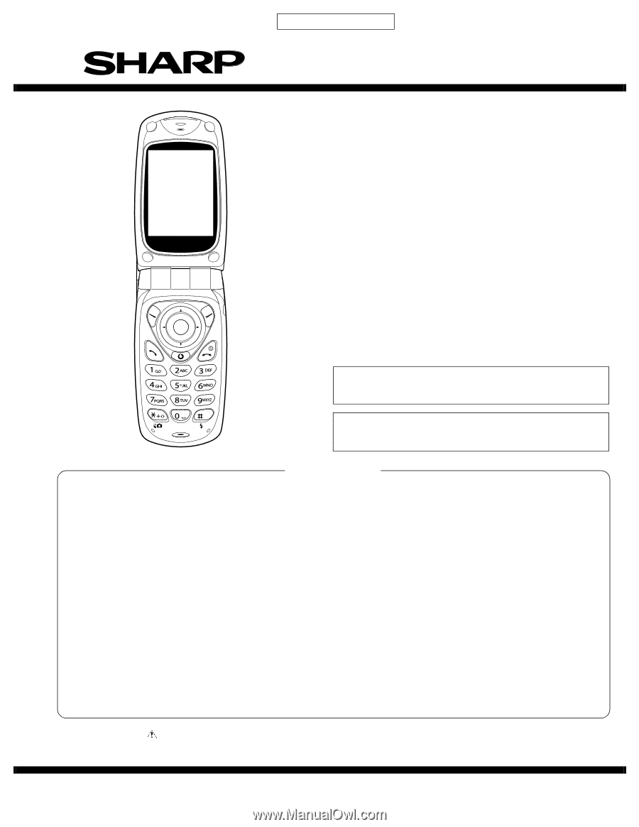
SERVICE MANUAL
GX20
No. S9311TQGX20/B
DIGITAL MOBILE PHONE
GX20
MODEL
SHARP CORPORATION
CONTENTS
Parts marked with "
" are important for maintaining the safety of the set. Be sure to replace these parts with specified ones for
maintaining the safety and performance of the set.
This document has been published to be used
for after sales service only.
The contents are subject to change without notice.
(INTERNAL MODEL NAME:
TQ-GX20E/G/R/T/S/H/EP/PP/W/B/D/A/Z/Q/L/F/C)
E : For U.K.
R : For Ireland
S : For Spain
EP: For U.K. (Prepaid)
W : For Sweden
D : For Greece
Z : For New Zealand
L : For Malta
C : For Switzerland
G : For Germany
T : For Italy
H : For Netherlands
PP: For Portugal (Prepaid)
B : For Hungary
A : For Australia
Q : For Egypt
F : For France
•
In the interests of user-safety the set should be restored to its
original condition and only parts identical to those specified
should be used.
•
Caution
Risk of explosion if battery is replaced by an incorrect type,
dispose of used batteries according to the instruction.