Sony VPL AW15 Operating Instructions - Page 72
VPL-AW15, Using adjustment pipe b: 150/175/200 mm 6 / 7 / 7
 |
UPC - 027242703094
View all Sony VPL AW15 manuals
Add to My Manuals
Save this manual to your list of manuals |
Page 72 highlights
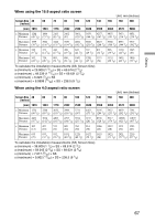
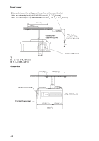
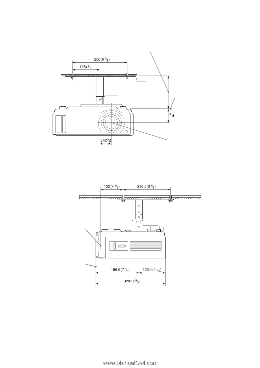
Front view Distance between the ceiling and the surface of the mount bracket Using adjustment pipe (b): 150/175/200 mm (6 / 7 / 7 7/8 inches) Using adjustment pipe (c): 250/275/300 mm (9 7/8 / 10 7/8 / 11 7/8 inches) Ceiling Center of the supporting pole The bottom surface of the mount bracket *d 6683.5(2(32/41)/2()V(PVLP-LA-WAW101)5) Side view Center of the lens Center of the lens Front of the cabinet (VPL-AW15 only) 72
-
 1
1 -
2
-
3
-
4
-
5
-
6
-
7
-
8
-
9
-
10
-
11
-
12
-
13
-
14
-
15
-
16
-
17
-
18
-
19
-
20
-
21
-
22
-
23
-
24
-
25
-
26
-
27
-
28
-
29
-
30
-
31
-
32
-
33
-
34
-
35
-
36
-
37
-
38
-
39
-
40
-
41
-
42
-
43
-
44
-
45
-
46
-
47
-
48
-
49
-
50
-
51
-
52
-
53
-
54
-
55
-
56
-
57
-
58
-
59
-
60
-
61
-
62
-
63
-
64
-
65
-
66
-
 67
67 -
 68
68 -
 69
69 -
 70
70 -
 71
71 -
 72
72 -
 73
73 -
 74
74 -
 75
75 -
 76
76
 |
 |
72
Front view
*d
63.5 (2
1
/
2
) (VPL-AW15)
68 (2
3
/
4
) (VPL-AW10)
Side view
Ceiling
The bottom
surface of the
mount bracket
Center of the
supporting pole
Center of the lens
Distance between the ceiling and the surface of the mount bracket
Using adjustment pipe (b): 150/175/200 mm (6 / 7 / 7
7
/
8
inches)
Using adjustment pipe (c): 250/275/300 mm (9
7
/
8
/ 10
7
/
8
/ 11
7
/
8
inches)
Center of the lens
Front of the cabinet
(VPL-AW15 only)